-
-
After these mods you will not believe it’s even the same pedal! This mod replaces key components in the signal path to turn your pedal into a serious tone machine.
-
Some of your components may look different than those shown in the install pictures, but the install instructions are still the same :)
-
If your pedal is currently under warranty, it will not be after these mods. This kit and the instructions do not include any warranty of any kind and you agree to hold harmless the seller of this kit against any and all claims.
-
-
-
If you are quite confident of your abilities you can remove all the components in one step then go through and replace them all. However, if this is your first time modding a pedal you should replace the parts one at a time, then test the pedal.
-
You don't need to completely put the pedal back together every time you test it as it will work perfectly fine with all the guts exposed. You may also like to hear the progress you are making as you go. Some parts will have a more drastic effect than others.
-
After the board is exposed it’s time to start removing components and replacing them with the new ones, as will be explained in the later steps.
-
Make sure the battery is removed and no cables or AC-adaptors are plugged in.
-
Don’t ever touch the soldering iron to the pedal while the pedal is plugged in.
-
-
-
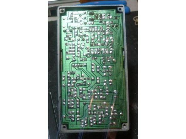
The PCB is pretty resilient, however, you need to be careful not to force the old components out of the holes as this can damage the traces and solder pads. Instead use a solder sucker and de-soldering braid to remove all the solder so that the old components are removed with ease.
-
I find that it is a good idea to clip the lead on the top side of the board before de-soldering.
-
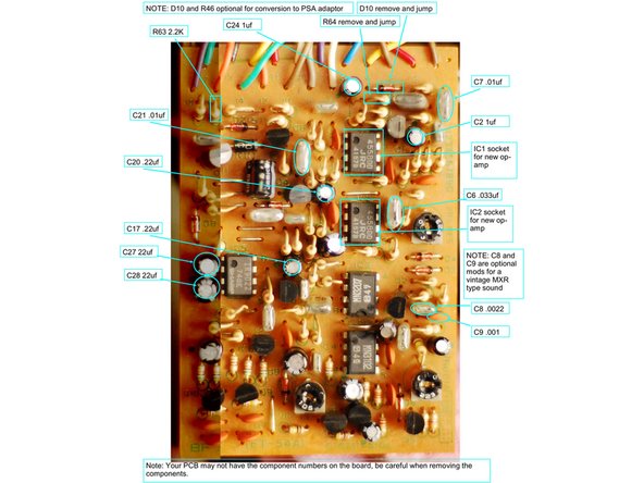
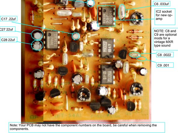
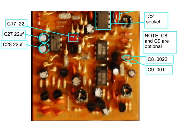
The IC’s and 22uf caps, must be inserted correctly in order to work. The chips have a notch that should line up with the notch shown on the board. Insert the chips the same way it’s shown on the left. For the 22uf caps at C27 and C28 the longer lead goes towards the + sign on the board.
-
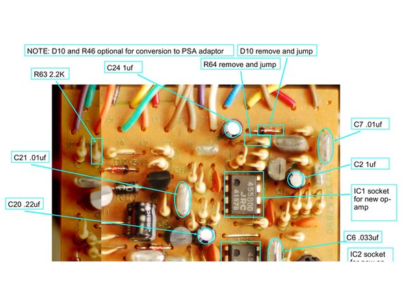
If your pedal is currently set up for ACA power you can convert it to PSA power by removing and jumping D10 and R64.
-
Changing C8 and C9 are optional and will give you a filter similar to a vintage MXR flanger.
-
-
-
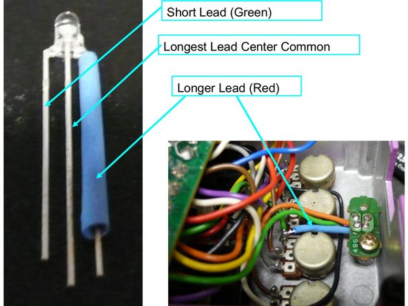
The LED in the kit has 3 leads. The shortest lead is the Green Light, the center lead is the common positive, the longer lead is the Red Light.
-
Insert the LED into the old LED holder with the short lead going to the green wire and the common (center) lead to the red wire, use the short piece of heat shrink to insulate the lead for the Red Light, bend it and solder to PIN 3 of the Depth Pot as shown to the left.
-
-
-
All of the caps in the kit for this step have a minimum voltage rating of 25V, but may be as high as 50V. Your pedal will still work just fine with 9V after these mods, you just won't damage it if you use up to 18V
-
Replace C39 with 100uf
-
Replace C29, C25, and C40 with 47uf caps
-
-
-
After swapping out the parts put your pedal back together and enjoy your new pedal!
-
Troubleshooting: Check to make sure that the soldering all looks shiny and that two pads aren't bridged by too much solder. Check to make sure no pads have lifted, if they have you can use a lead cut off a component to connect the broken connections. Check to make sure that none of the wires have come loose at the top of the PCB and fix them if so
-