
-
-
Start by sorting out all the parts in the kit, the parts list above will help!
-
Open up your pedal and take a look inside. (Your screwdriver might help with this.)
-
-
-
Expose the top side of the circuit board and find the parts that need to be removed.
-
It’s not a bad idea, especially if you're new to modding, to swap each component out one at a time making sure the pedal still works after replacing each one.
-
On the next step is a large diagram of the circuit board with highlighted components. The DS-1 has been pretty much the same pedal for over 20 years but there have been some minor changes to the layout. Your DS-1 may have the components in a slightly different place depending on when it was made.
-
-
-
Carefully remove the components using a de-soldering braid.
-
C1, C2, C3, C5, C8, C9, C10, C11, C12, C13, C14
-
D4, D5
-
R13, R14, R16, R35, R39
-
-
-
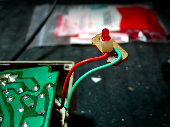
There is a small circuit board that holds the Red LED. Your kit has a bright orange LED to replace this with.
-
LED’s are polarized and only work one direction. The longer lead of the LED is the positive side orange wire.
-
-
-
If you decided to do all the mods at once your board will look something like this before you put it back together.
-
The capacitors and resistors are not polarized. Meaning it does not matter what direction you put them in. The diodes however are polarized and the band on the diode or the long lead on the LED goes on the side that the arrow is pointing to on the board.
-
You can test the pedal with all of it’s guts out but it may be a little noisier than normal because the metal enclosure is not providing any shielding for the circuit.
-
-
-
All of the caps in the kit for this step have a minimum voltage rating of 25V, but may be as high as 50V. Your pedal will still work just fine with 9V after these mods, you just won't damage it if you use up to 18V
-
Replace C23 with 100uf
-
Replace C15 with 47uf
-
-
-
After swapping out the parts put your pedal back together and enjoy your new pedal!
-
Troubleshooting: Check to make sure that the soldering all looks shiny and that two pads aren't bridged by too much solder. Check to make sure no pads have lifted, if they have you can use a lead cut off a component to connect the broken connections. Check to make sure that none of the wires have come loose at the top of the PCB and fix them if so
-


5 Comments
Is it possible to get a picture of the completed board with mods? Does one of the red LEDs go on D5?
Yes, one of the red LED's goes in D5, the shorter lead on the left side and the longer lead on the right.
Hi John - I ordered the Supreme mod kit, but this guide and the parts list doesn't seem to match up with the components I received. Am I missing something? Thanks!
Hey,
I have the same question, did you ever get a response?
I can’t seem to get a response.
Go ahead and email us directly at Fromelelectronics.com and we can get you taken care of!