-
-
WARNING Performing these modifications WILL void the warranty on your amp. Working on amps can be DEADLY if you do not take proper precautions.
-
Follow these instructions very carefully. If at any point in the mod process you are at all unsure of your ability to do these mods take your amp to a professional to be modded. You can also send your amp to me to be modded.
-
No Warranty - This kit and the instructions do not include a warranty of any kind. The modifications to your amplifier are at your own risk and you agree to hold harmless the seller of this kit against any and all claims
-
Tube amps contain parts that operate at very high temperatures and deadly voltages.
-
-
-
It’s a good idea to have all the parts and tools you will need laid out before starting in a well lit area
-
Remove the tubes, unplug the speaker, unplug the reverb from the reverb can (be sure to note which side is red and which side is black, remove the clips holding the reverb wire and power cable to the cabinet.
-
Remove the screws holding on the back panel and remove the panel. Then remove the chassis screws.
-
The chassis should slide out easily exposing the circuit board I find it easiest to work on the amp with the chassis completely removed from the cabinet.
-
-
-
WARNING: SKIPPING THIS NEXT STEP COULD RESULT IN DEATH
-
Using your multimeter set to DC measure the voltage from V1 pin 1 to ground. If the voltage is more than 10 VDC you need to drain the caps
-
Use a lead with alligator clips on both sides to connect pin 3 on V1 and pin 1 on V1, leave it connected until the voltage at V1 measures under 10 volts. This will slowly and safely drain DC from the amp.
-
-
-
Remove all the transformer leads and leads from the bone yard (where the filter caps are under the chassis. Be carful to note where each lead goes. I like to put a bit of masking tape on each lead and write the number it goes to in sharpie
-
Remove the three small PCB’s holding the controls for each channel by removing the knobs and washers from the chassis. Also remove the input jacks from the chassis
-
Remove the screws holding the main PCB. The main board should easily lift off the chassis
-
Be careful when removing parts from the circuit board, NEVER FORCE A PART OUT. Use a solder sucker and solder braid to remove solder. I like to clip the leads of the old parts when possible before removing the lead from the PCB. The PCB is fragile and too much heat can cause the solder pad to lift off the board.
-
-
-
Replace the tone stack caps at C2, C3, C4 and C7 C8 C9 on the PCB’s for each channel control.
-
Install: 300pf at C2, 0.1uf at C3, 0.047uf at C4, 300pf at C7, 0.1uf at C8, and 0.047uf at C9
-
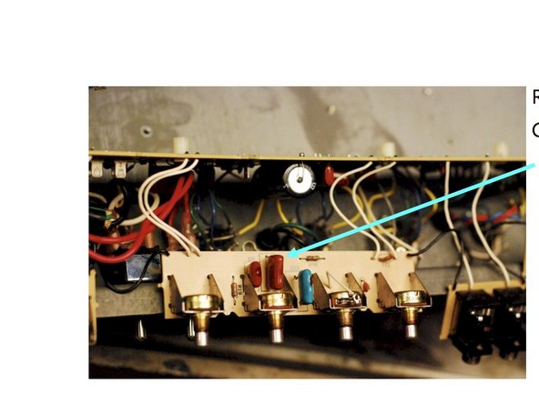
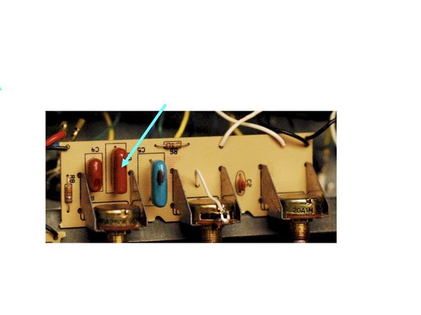
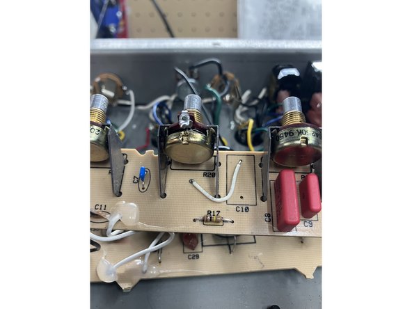
HIGHLY RECOMMENDED OPTION: For vintage Vibrolux tone controls remove C5 & C10. Move the wire from the back of the treble pots to the top hole of C5 and C10. See photo. You can always leave one side stock 'custom' tone controls and convert the other to this vintage spec. NOTE: photo only shows bright channel, but the other channel looks the same.
-
-
-
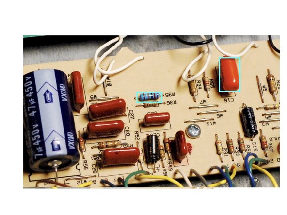
Remove R23, R11, R26, R35( empty), and C16
-
Install: 82k 1/2W at R23, 220k 1/2W at R11, 1K 1W at R26, 220k 1/2W at R35, and .0022uf at C16
-
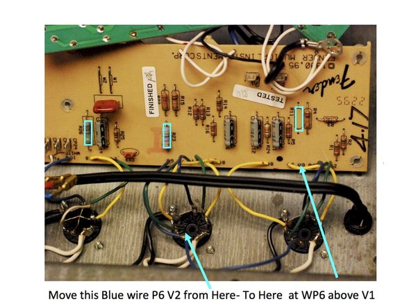
Disconnect the wire that is connected from Pin 6 of V1 to Pin 6 of V2 at pin 6 of V2. Connect it from Pin 6 of V1 to WP6 on the PCB.
-
-
-
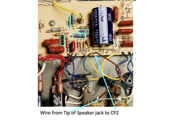
Remove R37, R42 Jumper, and remove solder from R41(empty)
-
Install 10k at R41, 470 ohm at R42, and 6K8 1W at R37
-
-
-
Remove solder from C20 and install 100pf in C20
-
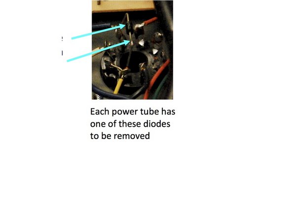
Remove diodes from CR6 and CR7. These are on the power tubes Pin 3 to ground and can just be clipped out.
-
-
-
The following two steps are only done if you ordered the Supreme Kit. If you ordered the Complete kit do not do these two Supreme Kit Only steps!
-
Make sure you mind the polarity of the caps, they must be inserted the right way or your amp will have problems which could be serious.
-
The circuit board will have a “+” sign closest to the hole where the positive lead of the cap goes. The axial caps have an indented ring on the positive side and a “-” sign in an arrow pointing to the negative side. For radial caps the longer lead is the positive side and there is a “-” sign in a band closest to the negative terminal.
-
On the small circuit board holding the Speed and Intensity controls, replace the 100/100 and 22/63 radial caps, minding the polarity
-
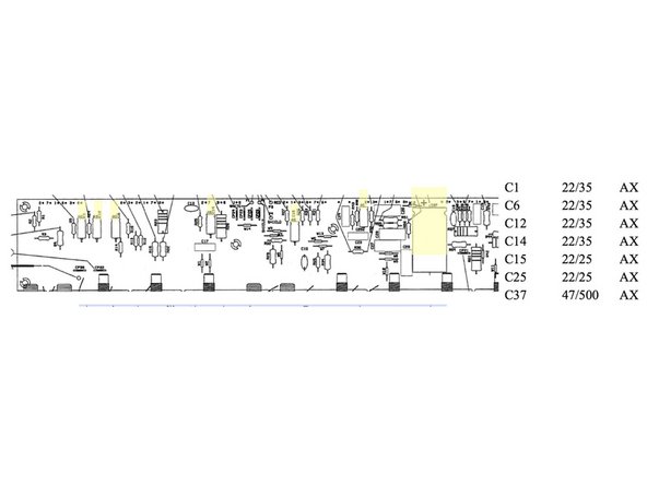
Replace the electrolytic caps on the main board, using the diagram and table to match the caps, again minding the polarity of the caps
-
-
-
Use a couple screws and nuts to secure all the circuit boards in the chassis, then flip the chassis over. Remove the rectangular cover( Dog House) pictured to the right
-
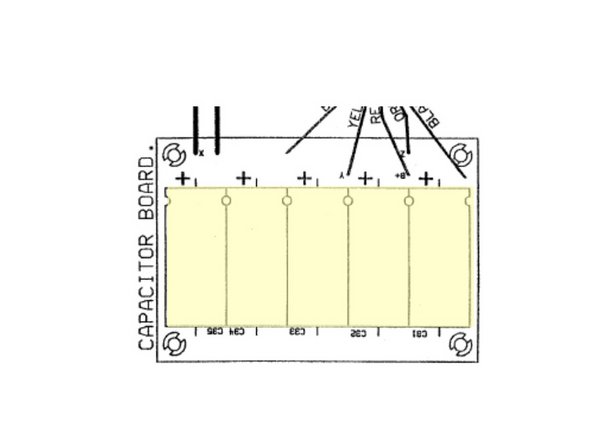
Replace the 22/500 caps, minding polarity.
-
Use Silicone to secure the caps to the PCB. Make sure that you have clipped all the excess leads from the solder side of the board and that all your new solder joints are secure before continuing
-
Put Dog house back together and turn the chassis back over
-
-
-
Double check all your work!
-
Carefully put the PCBs back into place making sure that none of the leads to the other boards or tube sockets have been disconnected and replace all the PCB mounting screws
-
Dress the transformer leads: Twist the green heater wires and position as shown. All other lead pairs should be twisted and cross each other at 90 degree angles to avoid noise, hum, and oscillation
-
Re-install the chassis the same way you took it apart, install the three small screws holding the chassis to the top of the amp (I like to turn the amp upside down when I do this),
-
Plug in the reverb and clips holding the power cord and reverb cable. Plug in the speaker cable. Install the back panel, then the 4 main chassis screws on the top of the amp
-
Replace the tubes and you should be ready to rock.
-
Almost done!
Finish Line


