
Tools
No tools specified.
Parts
- 1.5k metal film resistor
- 2.7k metal film resistor
- 10k 1/2 Watt Resistor × 2
- 91k 1/2 Watt Resistor × 2
- MLCC 270p Cap × 2
- Wima Cap .047 10mm × 2
- Wima .1 15mm Cap × 2
- 22uf 35v Radial Cap
- 22uf 25v cap (Supreme kit only) × 6
- Supreme kit only: 22uf/ 63V radial cap
- 4.7uf radial cap Supreme kit only
- 100uf 100v radial cap Supreme kit only
- Supreme kit only: 47uf/ 450V axial cap
- Supreme kit only - 22uf/ 500V cap
-
-
WARNING Performing these modifications WILL void the warranty on your amp. Working on amps can be DEADLY if you do not take proper precautions.
-
Follow these instructions very carefully. If at any point in the mod process you are at all unsure of your ability to do these mods take your amp to a professional to be modded. You can also send your amp to me to be modded.
-
No Warranty - This kit and the instructions do not include a warranty of any kind. The modifications to your amplifier are at your own risk and you agree to hold harmless the seller of this kit against any and all claims
-
Tube amps contain parts that operate at very high temperatures and deadly voltages.
-
-
-
Remove the screws holding on the back panel, unplug the speaker cable, and unplug the reverb cables from the chassis
-
Remove the three screws holding the chassis to the top of the cabinet
-
The chassis should now slide out the back
-
-
-
Check to see if there is DC voltage stored in your caps by measuring with a multimeter between V1 pin one and ground.
-
Use a lead with alligator clips on both sides to connect pin 3 on V1 and pin 1 on V1, leave it connected until the voltage at the filter caps measures under 10 volts. This will slowly and safely drain DC from the amp.
-
Repeat these steps until you measure less than 10VDC
-
FAILURE TO DO THIS STEP COULD CAUSE INJURY OR DEATH BY ELECTROCUTION!
-
-
-
Clip all zip ties
-
Remove the knobs, nuts, and washers from the front of the amp
-
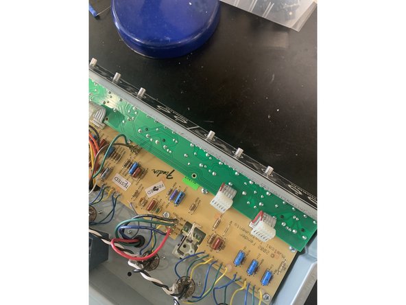
Disconnect the quick connects between the control PCB and main PCB. You should now be able to remove the control PCB
-
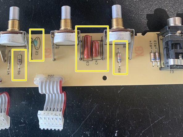
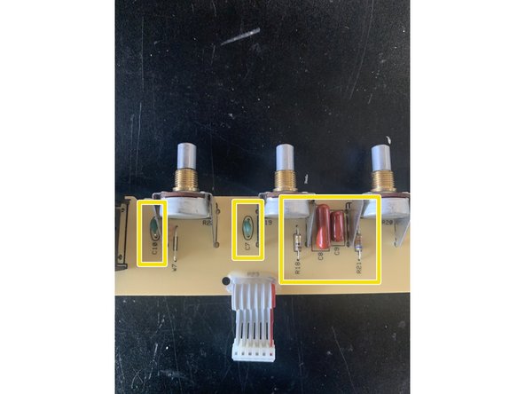
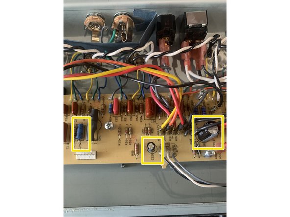
Replace C2 & C7 with 270pf mlcc. Replace C3 & C8 with 0.1uf. Replace C4 & C9 with 0.047uf. Remove C10.
-
Replace R6 and R18 with 91k. Replace R9 & R21 with 10k.
-
-
-
Disconnect the bias pot from the chassis. DO NOT clip the leads from the pot to the chassis.
-
Unscrew all of the screws holding the main PCB to the chassis.
-
You should be able to gently lift the main PCB on the side opposite the tubes so access the solder side of the main PCB
-
-
-
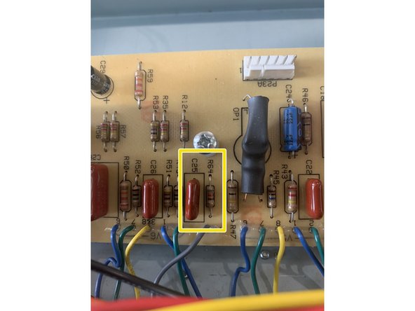
Replace R64 with 1.5k resistor.
-
Kits purchased before 9-4-2024 will have a .01 Wima cap for C25. After careful consideration and testing we believe that your tone will be better and more faithful to vintage Deluxes by leaving the stock value in which was the value used in vintage deluxes and new kits do not supply the .01 cap.
-
-
-
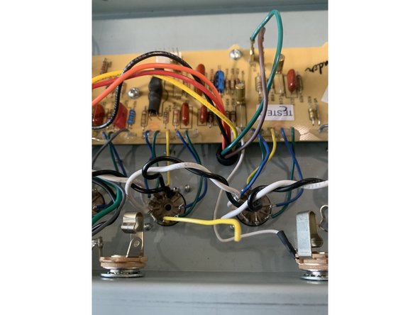
At V5 remove the wire marked 3 from the PCB to pin 3 of V5
-
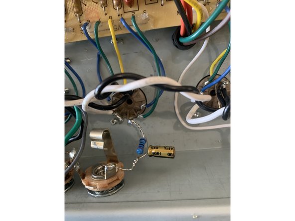
Solder the 22uf/ 50v cap to the 2.7k resistor. The voltage rating on this cap for the kits can be anywhere from 25V to 63V for this part depending on our supplier. This voltage rating is a maximum working voltage and any cap with a max voltage at least 10V would be fine here
-
Solder the positive side of the cap/ resistor to pin 3 of V5. Solder the negative side to the open ground lug on the Extension Speaker jack
-
The capacitor on this step need to be installed with the correct polarity. Failure to do this could cause catastrophic results
-
Axial capacitors have an indented ring on the positive side and a "-" sign in an arrow pointing to the negative lead. Radial Capacitors have a longer positive lead and there is a "-" sign in a band closest to the negative lead.
-
-
-
Only do this step if you purchased the Supreme kit. If you have the Complete kit skip this step and the one after it.
-
All of the capacitors on the next two steps need to be installed with the correct polarity. Failure to do this could cause dangerous and catastrophic results
-
To install the capacitors with the correct polarity the circuit board will have a "+" sign on it closest to where the positive lead of the cap should be installed
-
Axial capacitors have an indented ring on the positive side and a "-" sign in an arrow pointing to the negative lead. Radial Capacitors have a longer positive lead and there is a "-" sign in a band closest to the negative lead.
-
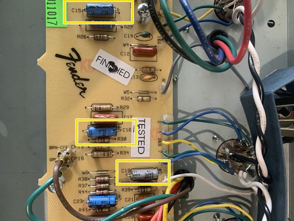
Remove C1, C11, C6, C15, C16, and C24, and replace with smaller 22uf/ 50v electrolytic caps. The voltage rating on caps for C1, C11, C6, C15, C16, and C24 in the kits can be anywhere from 25V to 63V for this part depending on our supplier. This voltage rating is a maximum working voltage and any cap at least 10V would be fine.
-
Remove C29 and Replace with 22uf/ 63v cap
-
Remove C19 and replace with a small 4.7uf/ 50v electrolytic cap.
-
Remove C36 and replace with a 100uf/ 100V cap.
-
-
-
Screw the main PCB back into the chassis and put the bias pot back to where it was.
-
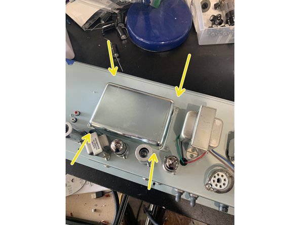
Flip the amp over. Remove the cover for the filter caps. It's a metal tray next to the output transformer - commonly called a "doghouse"
-
Remove the screws holding the filter cap PCB to the chassis so you can access the solder side of the PCB
-
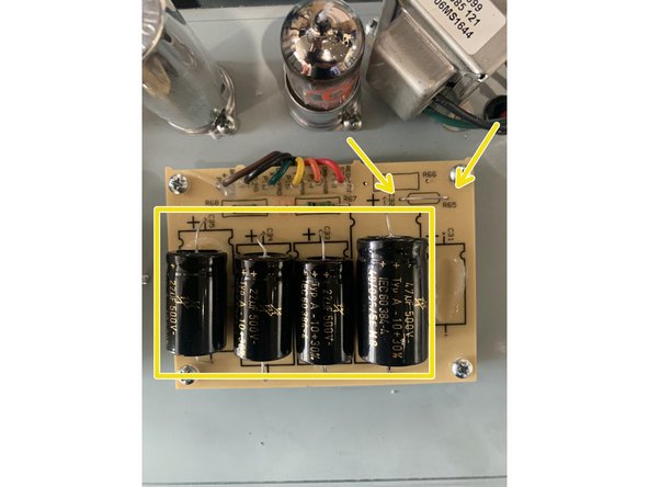
Remove C31, C32, C33, C34, C35, R65, and R66.
-
Install 47uf/ 500V in C32. Install 22uf/ 500V in C33, C34, and C35.
-
Bridge R65 with a lead that you removed from one of the filter caps.
-
-
-
Replace the control PCB taking care to pay attention to the quick connects
-
Attach nuts and washers on the pots and input jacks.
-
Re-install the chassis the same way you took it apart, install the three small screws holding the chassisto the top of the amp. Plug in the reverb jacks and the power cord strain relief.
-
Install the back panel and the 4 main chassis screws on top.
-
You are ready to rock!
-


Cancel: I did not complete this guide.
2 other people completed this guide.

6 Comments
Dear John , Antonio Monterroso here. I lost some the little solder pads. My station was running at 700 Fahrenheit, is there a troubleshooting guide when this happens?
Sorry for the delay! It's not the worst thing that can happen! You have a couple options. You can either carefully scrape the trace the pad connects to down to copper and solder the component to that or you can run a wire between the component and the next component the trace leads to. In our shop we do both depending on application. Worst case scenario you can take it to a tech or send the chassis to us to repair.
Question:
In the parts list and with the supreme kit I received one Wima .022 15mm Cap and one Wima .022 10mm Cap.
After going carefully through the instructions those two are left over.
Reading through the instructions again I can’t find where those two will go.
Can you tell me what to do with them?
Jurg Ragaz - Resolved on Release Reply