-
-
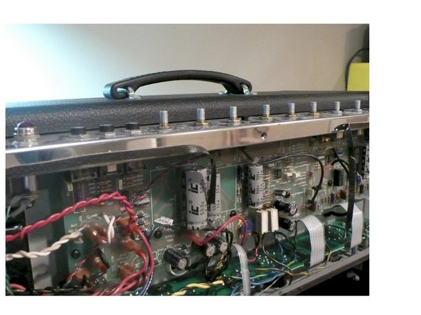
Follow these instructions to the letter. These mods can be done with the Chassis in the Cabinet and the PCB not completely removed. However I prefer to remove the chassis from the cabinet and remove both PCB’s from the chassis to perform the mods. It makes getting to the components easier and provides a more comfortable working environment
-
It’s a good idea to have all the parts and tools you will need laid out before starting in a well lit area
-
Remove the chicken head control knobs by loosening the set screws. Remove the nuts and washers holding the potentiometers and jacks on the top panel
-
Remove the screws holding on the back panel and remove the panel. If the back panel does not come off easily you can loosen the chassis screws on the side of the amp about a half turn each
-
-
-
The filter caps on your amp may be drained already but you must follow these steps to insure that any deadly voltage is removed from the amp before you begin work
-
Test the voltage across the filter caps. Set your multi meter to DC and measure the voltage across the positive and negative side of any of the filter caps. If the voltage reads higher than 10 volts, then you need to drain the cap
-
Using the insulated pliers to hold the 470 ohm 5W resistor touch one lead of the resistor to the negative side of the filter cap and the other to the positive side, leave the leads in contact with the power resistor for 30 seconds and measure again. Keep repeating this step until the voltage reads below 10V
-
-
-
Clip ALL of the wire ties
-
Remove all the knobs and nuts from the pots
-
Remove the smaller PCB which supports the tube sockets. The easiest way to do this is by removing the tubes, then removing the black screws which hold the sockets to the chassis
-
Unplug all the power and output transformer leads. As you remove each lead mark the wire with masking tape and a Sharpie so you will know where to plug it back in when you are putting the amp back together. I just mark the terminal number on the lead
-
Remove all circuit board standoff screws
-
Using gentle pressure on the top of the circuit board press the board down making sure it is not getting hung up on any wires until all the pots have cleared the top of the chassis then pull the board to you to expose the underside. DO NOT PUT PRESSURE ON ANY COMPONENTS INCLUDING THE FILTER CAPS WHEN MOVING THE BOARD
-
-
-
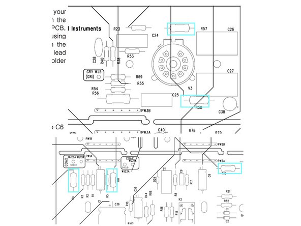
Remove R57 and R58 on the Tube PCB
-
Remove R4, R11, and R16
-
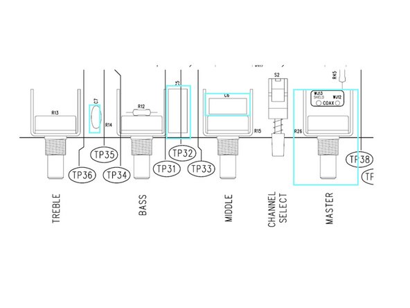
Remove Treble Cap C7. Bass Cap C5. Mid Cap C6
-
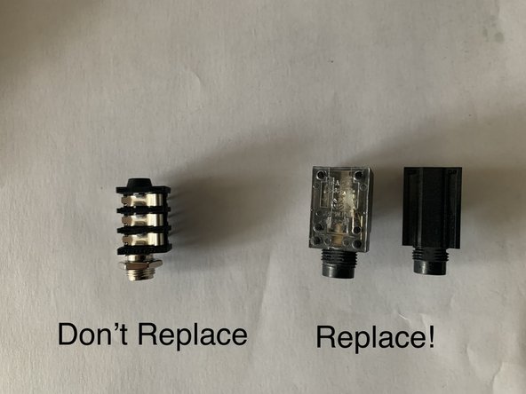
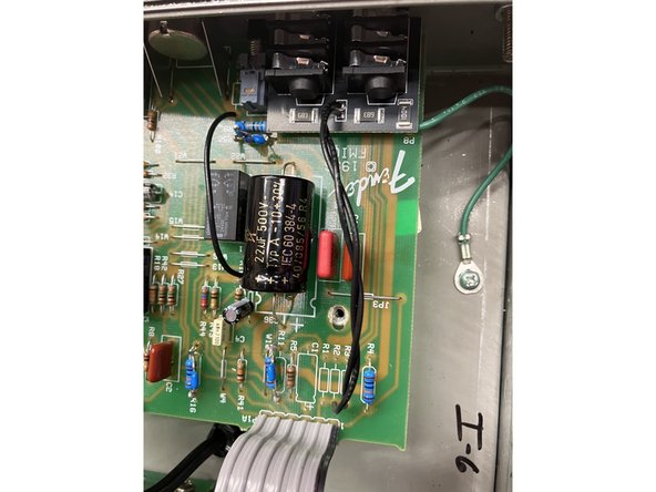
Remove the Input Jacks. It's easiest to remove the solder from the back side first then remove the jack. We do not recommend changing the input jacks if your amp came with "Neutrik" style jacks( See photo) as it can cause undue stress on the PCB
-
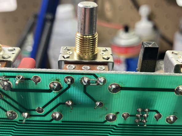
Remove the Master volume pot
-
Remove C31
-
-
-
Before removing the 470 ohm power resistors you may not have to. On older versions the resistors were mounted touching the circuit board and would occasionally overheat and burn the board
-
Fender later corrected this by mounting the resistors about 1/4” off the board. If your resistors are mounted correctly you wont have to replace them
-
-
-
At the Mid Tone Pot use a clipped off lead to bridge pins 2 and 3 which are the holes closest to the Power and Standby Switch
-
Install the .1 WIMA box cap at C5 (Bass Cap), the .015 WIMA box cap at C6 (Mid Cap) and at C7 install the 270p MLCC cap. After these mods your amp will not make sound with all of the tone controls all the way down. This is on purpose! What you're doing is changing the tone stack to a vintage style which gives you a greater range on the mid pot.
-
At R57 install the 91K Resistor. Install 100K resistors at R58, R4, R11, and R16
-
Install the 100k audio pot where the master volume was
-
Remove C52 just next to the reverb pot. I recommend clipping both leads from the component side of the PCB
-
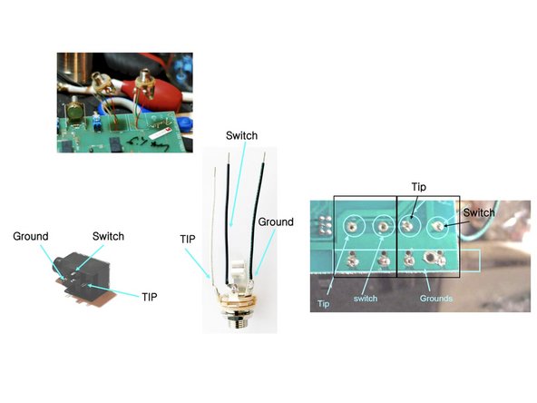
Install the new input jacks as shown in the pic and as follows if your kit was bought before 8-22-24 and came with open frame jacks.
-
There are two versions of the Blues Deluxe stock jacks, in each case there are three wires to connect. The Ground, switch, and Tip. If your old jacks look like the one on the left wire according to where the old pins were. If your PCB looks like the one on the right then wire for that configuration
-
Install 100uf/ 450v capacitor in C31
-
-
-
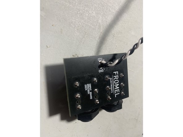
Follow the instructions below if your kit came with the Fromel input jack PCB
-
Remove R3, R2, and R1.
-
Twist the120mm leads.
-
Solder one end of the twisted pair to the jack PCB at SIG and GND as shown in the photo and the other ends into R2 and R3: the lead from the jack PCB SIG goes to the tube side of R2 and GND goes to the ground side of R3
-
Some runs of the PCB will require you to solder the jacks, two 68k resistors, and 1M resistor before installing the new input jack PCB. Follow the direction printed on the input jack PCB.
-
-
-
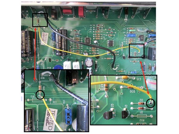
This mod will allow the use of the Master Volume knob on both drive and clean channels
-
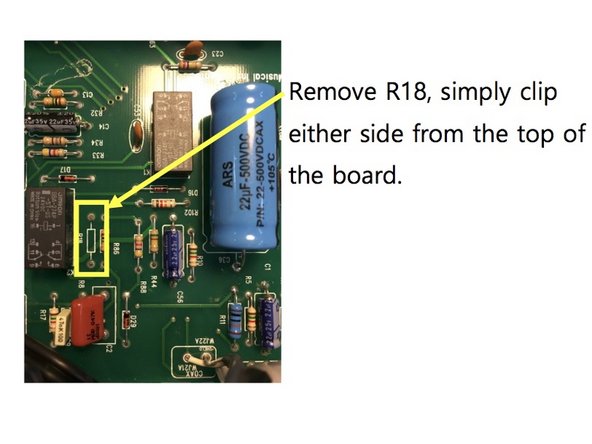
Remove R18, simply clip either side from the top of the board
-
Use the provided length of wire and wire as in the photo. Wire the bottom side of R45 located below the Master Volume pot to the right side of D2 located a few inches below the drive pot
-
-
-
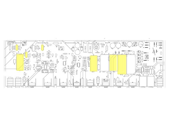
Only follow this step if you purchased the Supreme kit
-
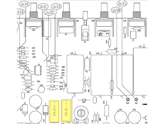
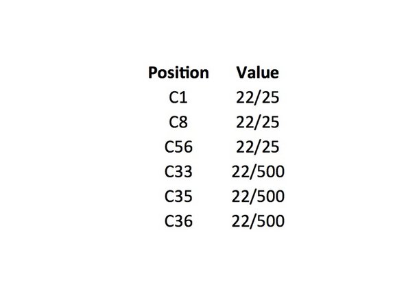
In one of the pics is the chart for all the caps and where they go with position numbers. Below is the board layout. Make sure you mind the polarity of the caps, they must be inserted the right way or your amp will have problems which could be serious
-
The circuit board will have a “+” sign closest to the hole where the positive lead of the cap goes. The axial caps have an indented ring on the positive side and a “-” sign in an arrow pointing to the negative side. For radial caps the longer lead is the positive side and there is a “-” sign in a band closest to the negative terminal
-
The voltage rating on caps for C1, C8, and C56 in the kits can be anywhere from 25V to 63V for this part depending on our supplier. This voltage rating is a maximum working voltage and for where they are used in the circuit they will see less than 10V
-
-
-
Carefully put the PCB back into place making sure that the pots, switches, and input jack all line up with the control panel and replace all the PCB mounting screws
-
Re-install the small PCB that holds the tubes. Make sure all the ribbon cables have a smooth path with no kinks or sharp turns in the cable
-
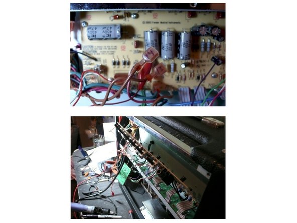
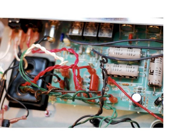
Dress the Transformer leads!!! Poor lead dress is a large part of the noise in an amp. We are going to use standard wiring techniques for proper tube amp design. Twist the green heater wires and position as shown. All other lead pairs should cross each other at 90 degree angles to avoid noise, hum, and oscillation
-
Re-install all the washers for the pots and jacks use the isolation washers on the input jacks as shown. Do not over tighten the jacks for the effects loop or footswitch
-
Plug the speaker back into the speaker jack. Re-install the control knobs and install the washer and nut on the new input jack. DOUBLE CHECK ALL YOUR WORK. Replace the back panel and make sure to tighten the chassis screws if you loosened them.
-
ENJOY YOUR NEW AMP!
-