Tools
-
-
This mod is meant to be done in conjunction with other Fromel mod kits, though it can be done on it's own. If you're doing it on it's own please follow the directions and warnings from the Blues Junior MIM mod kit Steps 1 - 7 first before continuing on with this mod.
-
This tube board is not compatible with any other bias mods - Bill M, etc. If your amp has mods other than the Fromel Supreme, complete, and standby mods it will need to be returned to stock before proceeding with the tube board installation.
-
DO NOT REUSE THE RIBBON CABLE! We provide instructions for replacing it and can't guarantee a successful mod if you don't!
-
-
-
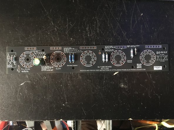
Install components from the kit on the tube board - tube board is marked where they go. Mind the polarity on the cap and diodes.
-
Earlier versions of the board had the components installed so if you have an earlier version of the kit with either through hole or SMD components you can skip this step.
-
R10 may be anywhere between 150 and 180 ohms depending on which version of the kit you have. Any of those values will work fine in R10.
-
-
-
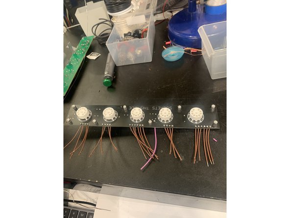
Install the 9 pin tube sockets in the tube PCB. I like to set them by soldering one pin on the socket side to hold the socket in place when flip it over
-
Solder the tube sockets. Make sure that they're seated evenly.
-
The sockets need quite a bit of heat to get a good solder joint with the tube PCB's plated through holes. We use an 800 degree chisel tip iron and it takes several seconds for the joint to be done. This is a spot with a smaller iron you'd be hard pressed to burn out the pad.
-
-
-
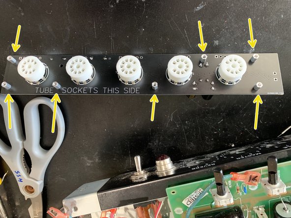
Remove the standoffs from the stock tube PCB and install in the new PCB
-
There will be one standoff from the stock tube board that doesn't get used
-
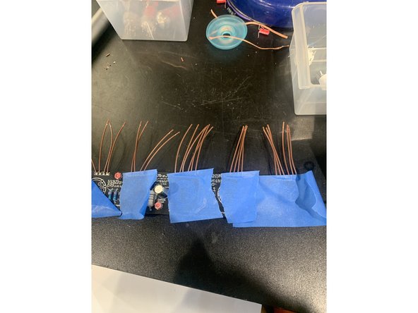
Insert the new wires into the component side of the PCB, including the 4" wire at P1. I like to use painters tape to hold them in place while I flip it over and solder them.
-
Trim the ends after soldering to make sure none of the connections will short out on the chassis
-
-
-
DO NOT REUSE THE RIBBON CABLE! We provide instructions for replacing it and can't guarantee a successful mod if you don't!
-
Desolder and disconnect the two green heater filament wires WJ8 and WJ9 from the stock Tube PCB
-
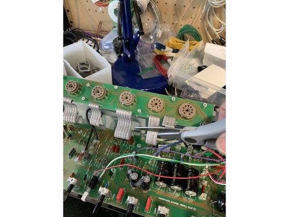
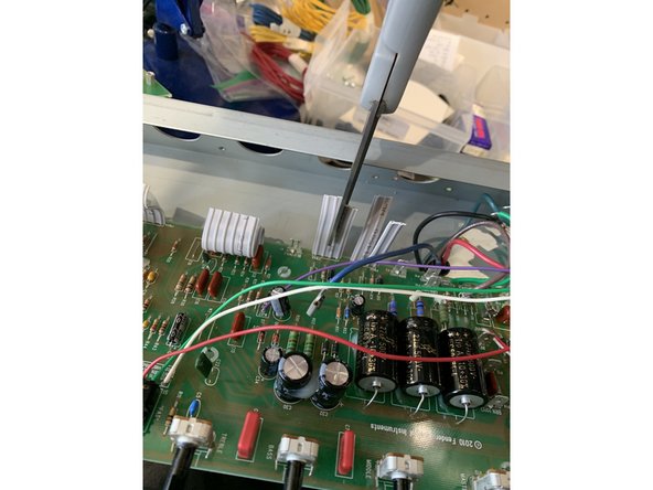
Clip all of the ribbon cables in half, then on the main PCB cut them lengthwise all the way to the PCB separating them into two leads. Clip the ribbon cable leads extending past the pad on the solder side and add some leaded solder to the pads- makes it easier to remove without damage.
-
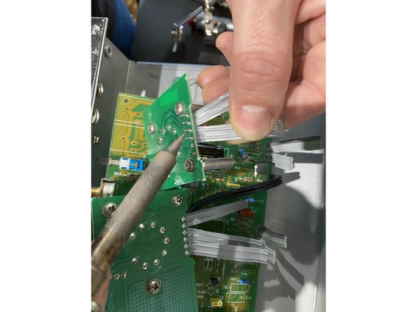
Gently tug on one of the separated ribbon cables while rocking back and forth and heating the solder connection with your soldering iron.
-
Remove all of the solder from the pads on the main PCB
-
-
-
For Cathode bias Blues Jr IV's see the next step
-
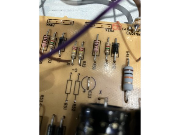
Remove R51, R52, and C33
-
Remove R8
-
Jumper C33
-
Remove R54 and R55
-
-
-
Remove and jump C10 and C33
-
Clip resistors R54 and R55
-
Remove R8
-
-
-
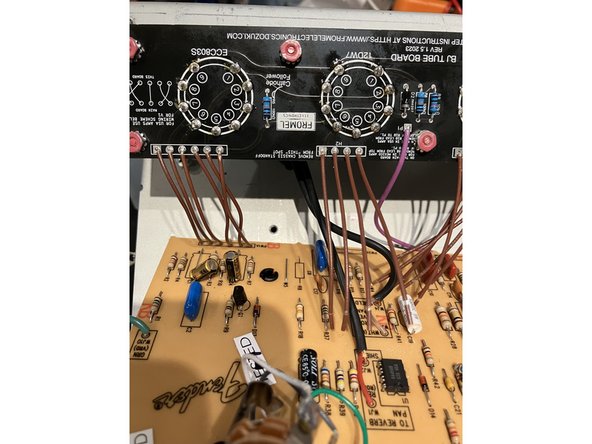
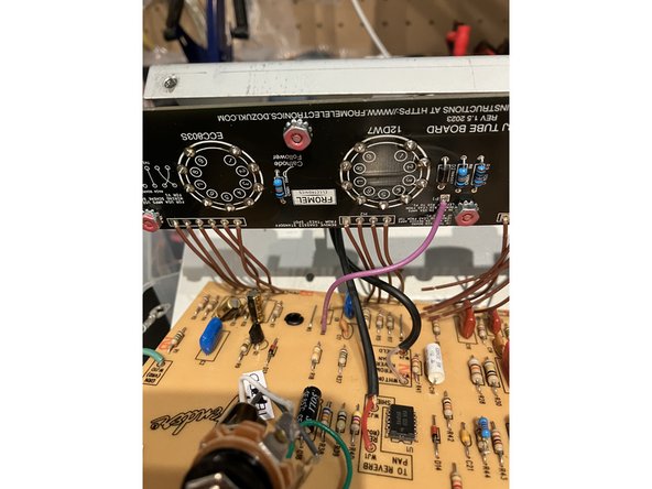
Insert the wires coming from the Tube PCB into the solder holes on the Main PCB and solder on the tube socket side. I find it's easiest to do this by soldering a few at a time and working my way from left to right
-
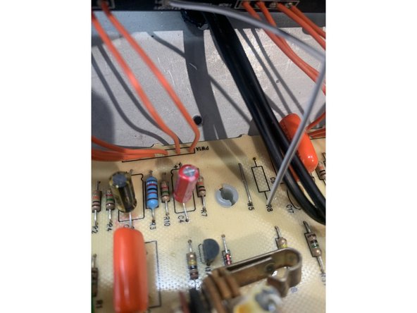
Solder the wire coming from P1 on the tube board to the top hole of R8( top when looking at the amp from the control side)
-
Trim the ends after soldering to make sure none of the connections will short out on the chassis
-
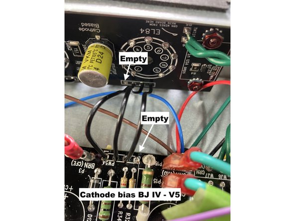
VERY IMPORTANT! Wiring V5 on the Cathode biased Blues JR IV's is a little different, you're only going to be connecting 3 wires. PW5A 1, 2 ,3 connect to PW5B 2, 3, 4 respectively. PW5A-4 and PW5B- 1 are left empty. See pic.
-
-
-
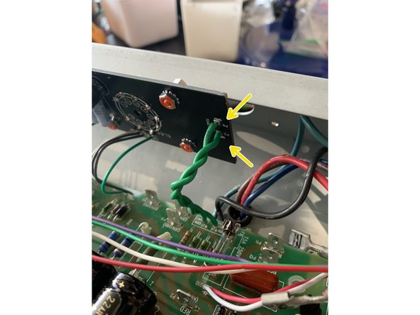
Twist the green heater wires that you removed from WJ8 and WJ9 together and install on the new tube PCB at P5 and P6 soldering on the tube socket side
-
-
-
That's all for installing the new Tube PCB. Follow the steps in the main mods directions to put your amp back together and enjoy great tone!
-
Cancel: I did not complete this guide.
2 other people completed this guide.
One Comment
Completed the tube board with supreme mods and Mercury magnetics Transformers, da.mn sounds amazing!!
Thank you!
Jose Martin - Resolved on Release Reply

