
Tools
Parts
- 33k 1/4w metal film resistor
- MLCC 270p Cap
- Wima .1uf 10mm cap
- Wima .015uf 10mm cap
- 100uf 450v Axial Capacitor
- 3 inch stranded tinned wire × 2
- 1500pf MLCC cap
- 22uf cap 25v min.
- 2.2uf cap 25v min.
- Supreme kit only: 22uf/ 450V axial cap × 3
- Fromel input jack PCB
- 100uf or 80uf cap 400v min
- 22uf or 20uf cap 400v min × 3
-
-
These instructions are for the kit available for purchase here: https://fromelelectronics.com/collection...
-
WARNING Performing these modifications WILL void the warranty on your amp. Working on amps can be DEADLY if you do not take proper precautions.
-
Follow these instructions very carefully. If at any point in the mod process you are at all unsure of your ability to do these mods take your amp to a professional to be modded. You can also send your amp to me to be modded.
-
No Warranty - This kit and the instructions do not include a warranty of any kind. The modifications to your amplifier are at your own risk and you agree to hold harmless the seller of this kit against any and all claims
-
Tube amps contain parts that operate at very high temperatures and deadly voltages.
-
-
-
Unplug the amp and place on a level surface
-
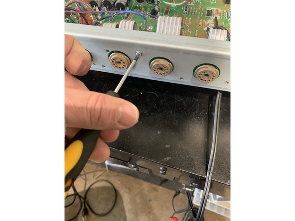
Remove the chicken head control knobs by loosening the set screws. Remove the nut and washer holding the input jack on the top panel
-
Remove the screws holding on the back panel and remove the panel. If the back panel does not come off easily you can loosen the chassis screws on the side of the amp about a half turn each
-
-
-
Drain the Filter Caps: The filter caps on your amp may be drained already but you must follow these steps to ensure that any deadly voltage is removed from the amp before you begin work.
-
Test the voltage across the filter caps. Set your multimeter to DC and measure the voltage across the positive and negative sides of any of the filter caps. If the voltage reads higher than 10 VDC, then you need to drain the caps.
-
Use a lead with alligator clips on both sides to connect pin 3 on V1 and pin 1 on V1, leave it connected until the voltage at the filter caps measures under 10 volts. This will slowly and safely drain DC from the amp.
-
-
-
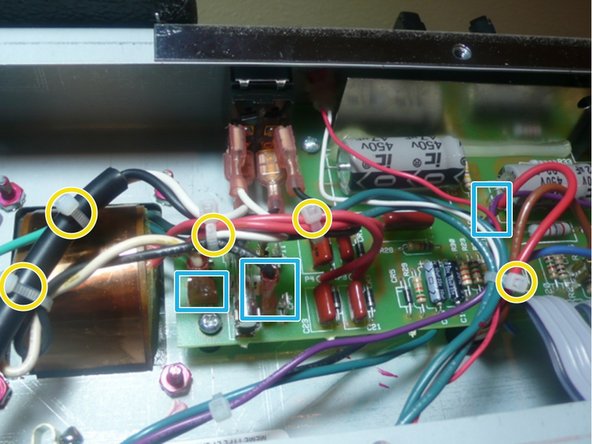
Clip all of the wire ties
-
Unplug all the transformer leads by pulling firmly with steady pressure gently rocking the lead terminal from side to side.
-
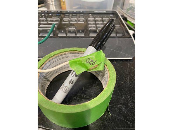
As you remove each lead mark the wire with masking tape and a Sharpie so you will know where to plug it back in when you are putting the amp back together. I write the terminal number on the lead.
-
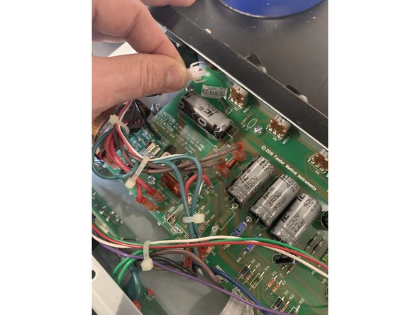
Remove the pilot LED from the top of the chassis. It should just unsnap when pulled while squeezing the white LED holder
-
-
-
Remove all of the screws holding the tube pcb board
-
DIsconnect footswitch and speaker jack assembly from the chassis
-
Gently, with putting as little strain and lateral motion on the ribbon cable, lift the tube board and footswitch/ speaker jack assembly up and free of the chassis
-
-
-
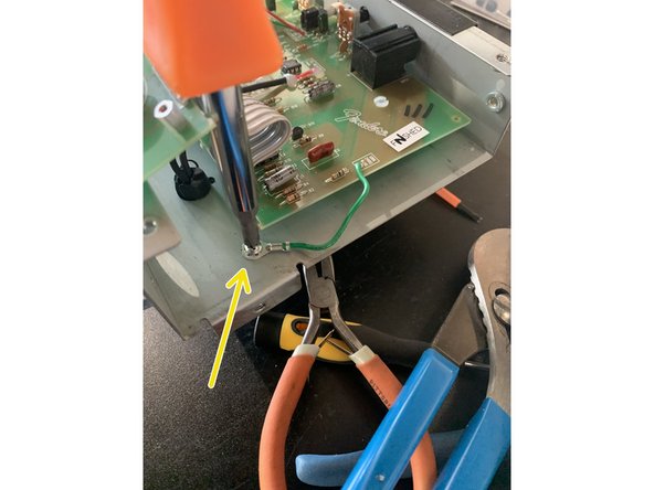
Remove all screws holding the PCB to the chassis and remove the grounding lug screw.
-
Pull gently on the board to make sure that it is not stuck to any of the standoffs that were holding the circuit board screws.
-
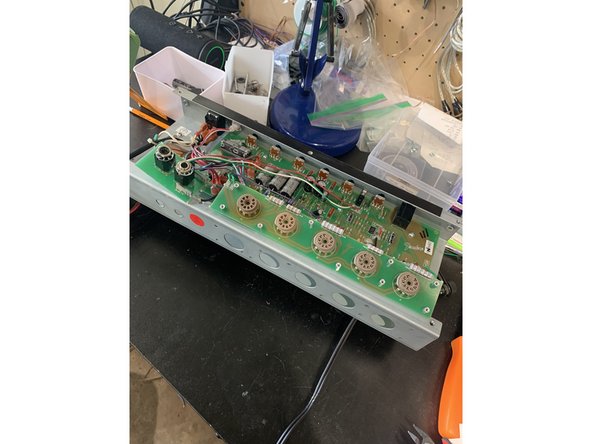
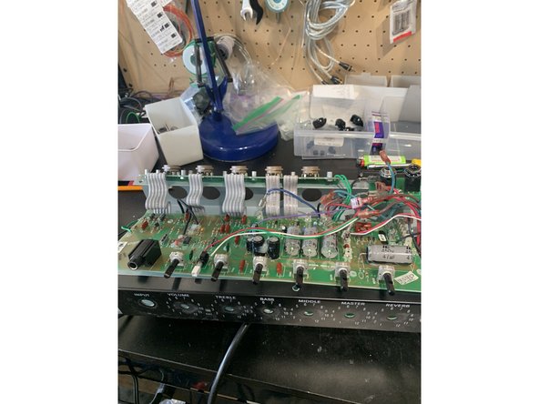
Press the wires from the output transformer as far away from the board and as close to the chassis as possible. The board needs to come down toward the bottom of the amp before the pots will clear the top of the chassis as shown.
-
Using gentle pressure on the top of the circuit board press the board down making sure it is not getting hung up on any wires until the pots have cleared the top of the chassis then pull the board to you to expose the underside.
-
DO NOT PUT PRESSURE ON ANY COMPONENTS INCLUDING THE FILTER CAPS WHEN MOVING THE BOARD.
-
-
-
Be careful that your soldering iron is not too hot. The solder pads on the PCB are prone to curling and separating from the PCB, remove the components with care, never using force. We recommend using de-soldering braid as solder suckers can rip the pads off the PCB.
-
For axial components (leads on each side), it is best to clip the leads on the front of the PCB then remove the remainder of the lead and solder from the backside carefully with de-soldering braid. For radial components (both leads on bottom) it is best to remove the solder first.
-
The ribbon can can be fragile so it's best to move it as little as possible
-
-
-
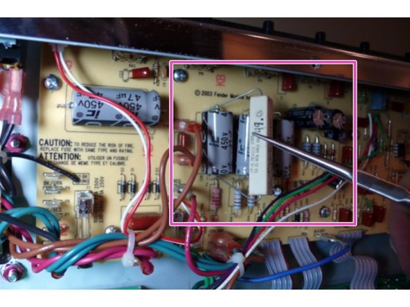
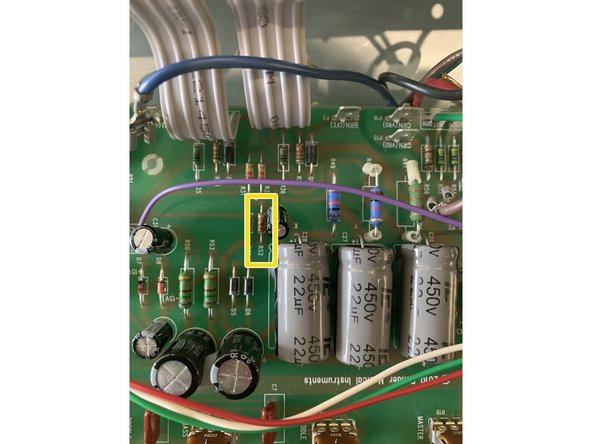
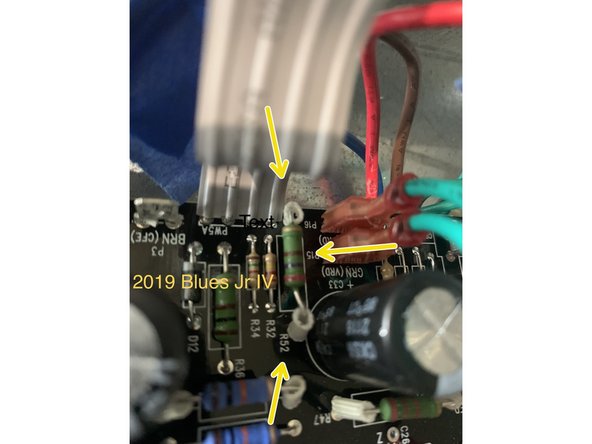
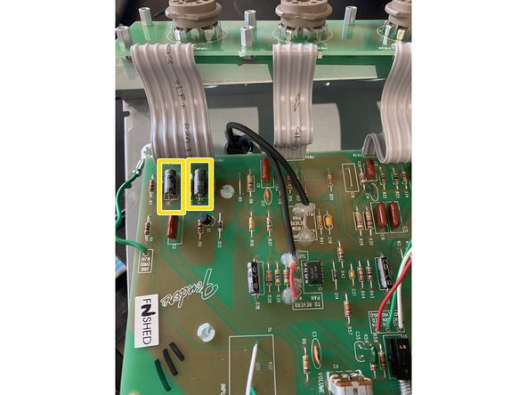
Remove R52
-
Install 33k bias resistor in R52
-
You can skip installing the 33k bias resistor in R52 if you are also installing the Fromel Tube Board
-
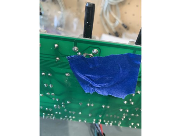
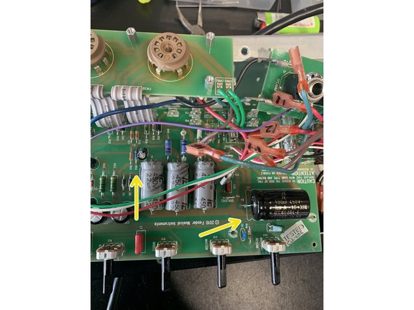
Newer Blues Jr IV's are cathode biased and do not need this mod. If your amp has a Black PCB and says (c) 2019 Fender Musical Instruments and/ or there is a 270 ohm resistor in R52 - DO NOT do this step. Shown in the picture.
-
-
-
Remove input jack. This part is snapped into the PCB and then soldered. I find it's easiest to remove the solder from the back side first and then remove the jack
-
-
-
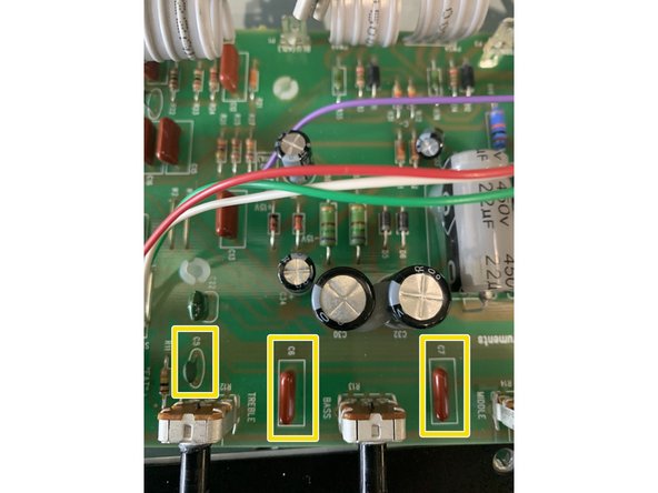
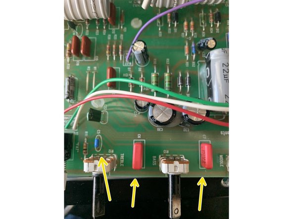
Install 270pf MLCC at C5
-
Install .1uf Wima at C6
-
Install .015uf Wima at C7
-
At the Mid tone pot - R14- Bridge pins 2 and 3 which are the closest to the Master Volume pot. Use a clipped lead from any component you've installed. I use a piece of masking tape to hold the lead in place for soldering.
-
After these mods your amp will not make sound with all of the tone controls all the way down. This is on purpose! What you're doing is changing the tone stack to a vintage style which gives you a greater range on the mid pot.
-
-
-
Install 100uf or 80uf cap in C25
-
Electrolytic caps like the cap at C25 are polarized and will only work if they are installed in the correct orientation. The lead with the "+" symbol closest to it on the side that's indented needs to be in the hole marked "+" on the PCB.
-
-
-
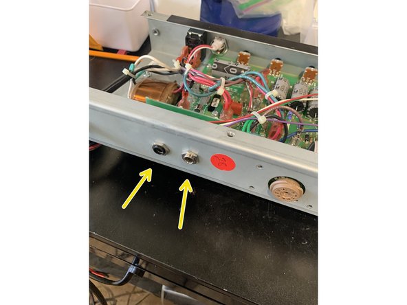
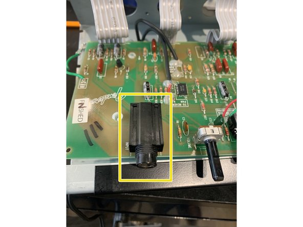
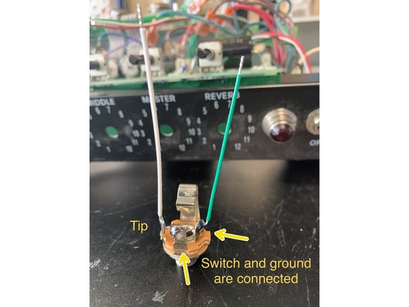
If your kit came with open frame jacks like the photo follow the instructions below
-
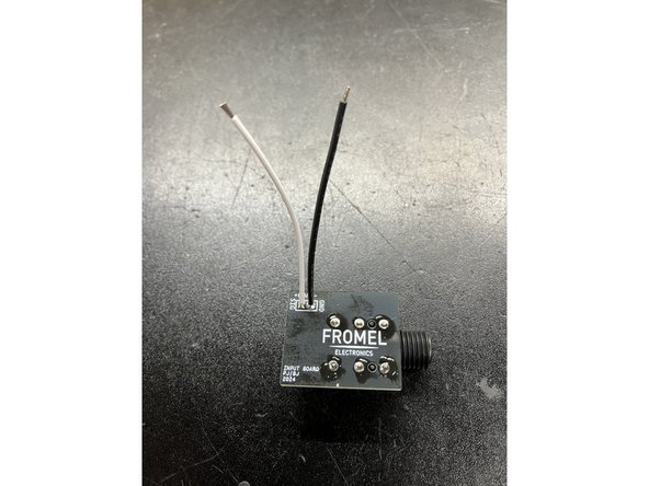
Solder the wires included in the kit to the jack as shown. The ground wire should bridge the ground and middle( switch) lugs.
-
Solder the jack wires to the PCB with the ground/ switch connection closest to the top of the board( control side) and the tip wire closest to the bottom( tube side)
-
-
-
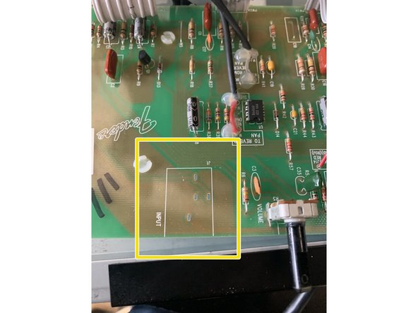
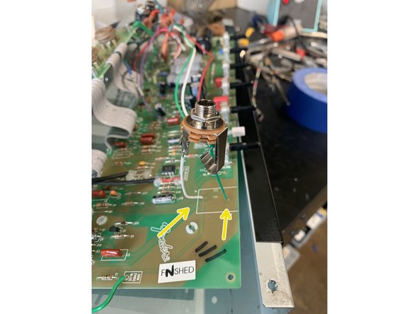
If your kit came with the Fromel input jack PCB follow the instructions below
-
Remove input jack. This part is snapped into the PCB and then soldered. I find it's easiest to remove the solder from the back side first and then remove the jack.
-
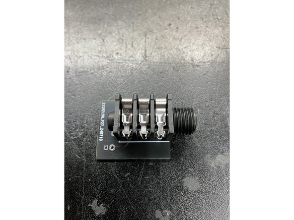
Solder the jack to the jack PCB oriented as shown in the photo with the jack outline side being where the jack is mounted.
-
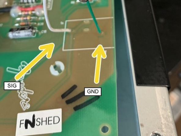
Attach leads to the jack PCB at SIG and GND
-
Connect the leads from the jack PCB to the Blues Jr main PCB at the points shown in the photo
-
-
-
If you have a Blues Jr. III with the “Sparkle Mod” you won’t have a cap at C9. Install the .0015uf cap at C9 if you want to change your “Sparkle Mod” back to stock.
-
If you have a Blues Jr IV to remove the 'Sparkle Mod" you'll need to solder the .0015 cap to pins 1 and 3( the outside pins) of the master volume pot.
-
-
-
Only follow this step if you purchased the Supreme Mod Kit
-
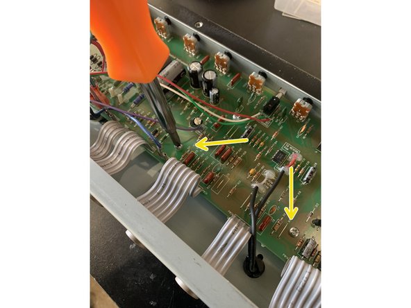
Remove C1 and C4 on the left side of the board near the first ribbon cable
-
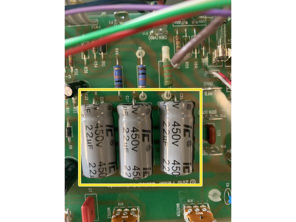
Remove C26, C27, and C28
-
Install 22uf/ 25v min cap in C1 and a 2.2uf/ 25v min cap in C4
-
Install 22uf or 20uf 400v min caps in C26, C27, and C28
-
The voltage rating on caps for C1 and C4 in the kits can be anywhere from 25V to 63V for this part depending on our supplier. This voltage rating is a maximum working voltage and for where they are used in the circuit they will see less than 10V
-
-
-
If you purchased additional mod kits refer to those now BEFORE starting to put your amp back together
-
Carefully put the PCB back in place making sure that the pots, fat switch, and input jack all line up with the control panel and replace all the PCB mounting screws
-
Put the tube PCB back in place making sure to not stress the ribbon cables while doing so and that there are no kinks or sharp turns in the ribbon cable
-
Dress the transformer leads!! Poor lead dressing will contribute to the noise in an amp. Instead of replacing the cable ties we removed we're going to use standard wiring techniques for proper amp lead dress. Twist all AC pairs together: twist green wires together, red, and brown. All twisted pairs should cross each other at 90 degree angles
-
Reinstall the the small board with the speaker and footswitch jacks, the lock washer goes on the inside between the chassis and the jack. Don't overtighten the nut or you'll strip the threads.
-
Glue all the caps to the board as well as the lead wire for the reverb with silicone caulk.
-
Reinstall the control knobs and install the nut and washer on the input jack. Replace the back panel and install the washer and nut on the new input jack
-
ENJOY YOUR NEW AMP!
-


Cancel: I did not complete this guide.
2 other people completed this guide.

13 Comments
Just installed BJ supreme mod kit and BJ tube board. The amp is MIM so i followed the guide for MIM install. once amp is powered and tubes heat up the amp has a very loud squeal...none of the pots affect it . squeal only quits when V3 is removed. Any ideas where to look?
rehaywood@bellsouth.net
Ricky Haywood - Open Reply
After following every step, the amp works but is noisy, can't find the issue. I have MIM ver IV, I retraced every step but still noisy. The only thing I haven't done is taking the board into the chasis, I'm testing everything out, but other than that, everything is just as described... anyone? Please help.
Just like you said, I needed to build everything up and install it inside the cab. Now it sounds great and noise-free! Thank you so much, John!
Jorge -
Sounds like a ground is not connected, make sure the green wire from the main PCB to the chassis is connected. Feel free to send some pics of your work to info@fromelelectronics.com if you can't figure it out.