
Tools
No tools specified.
Parts
- 1u Cap
- MLCC 100p Cap
- MLCC 270p Cap
- 470pf MLCC cap
- 2.7k 1/2 Watt Resistor
- 10k 1/2 Watt Resistor
- 56k 1/2 Watt Resistor
- 150k 1/2 Watt Resistor
- 470k 1/2 Watt Resistor × 2
- 1m 1/2 Watt Resistor
- .022uf Mallory 150 × 2
- 220 ohm 3W Resistor
- 100 Ohm 1W Resistor
- 22uf/ 400v radial 5mm lead × 2
- 100uf/ 400v radial 7.5mm lead
-
-
WARNING Performing these modifications WILL void the warranty on your amp. Working on amps can be DEADLY if you do not take proper precautions.
-
Follow these instructions very carefully. If at any point in the mod process you are at all unsure of your ability to do these mods take your amp to a professional to be modded. You can also send your amp to me to be modded.
-
No Warranty - This kit and the instructions do not include a warranty of any kind. The modifications to your amplifier are at your own risk and you agree to hold harmless the seller of this kit against any and all claims
-
Tube amps contain parts that operate at very high temperatures and deadly voltages.
-
Early versions of this amp that don't have a separate tube PCB( The tubes are mounted with the components all on one PCB) have PCB's that are EXTREMELY fragile and we don't recommend doing the mods if you have this version of the amp and don't have any experience modding amps. however we have included instructions for this version too.
-
-
-
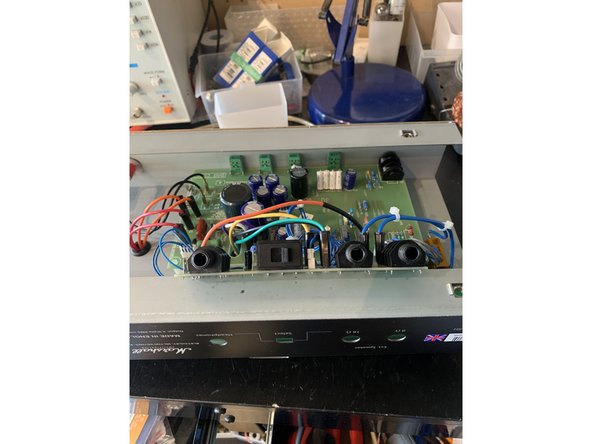
Unplug the amp and place on a level surface
-
Remove the four screws holding the chassis to the cabinet and remove the chassis and place it in a well lit work area
-
-
-
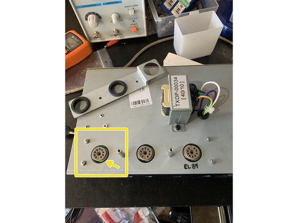
Turn the amp over so the tube sockets are facing you
-
Check to see if your caps are charged, set your multi-meter to DC and measure the voltage at pin 1 of V1
-
Pin 1 is the first tube pin counter clockwise of the space
-
If you measure more than 15VDC, you need to drain the caps. If there are less than 15VDC you may proceed to the next step
-
Using an insulated wire short V1 pin 1 to the chassis.
-
-
-
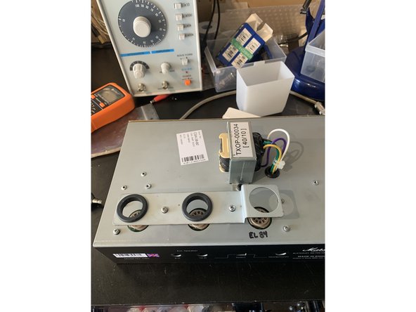
Turn the chassis over
-
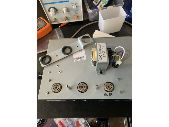
Remove the two screws holding the tube guard and remove the tube guard and set it aside.
-
Unscrew the two stand offs and the four screws holding the tube PCB
-
Turn the chassis back over
-
-
-
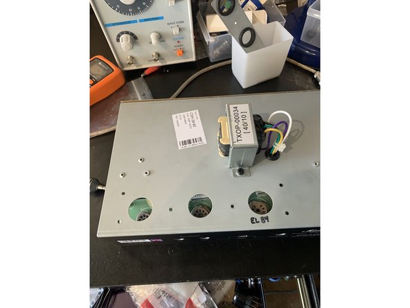
Remove the two red and one black speaker and headphone jack nuts
-
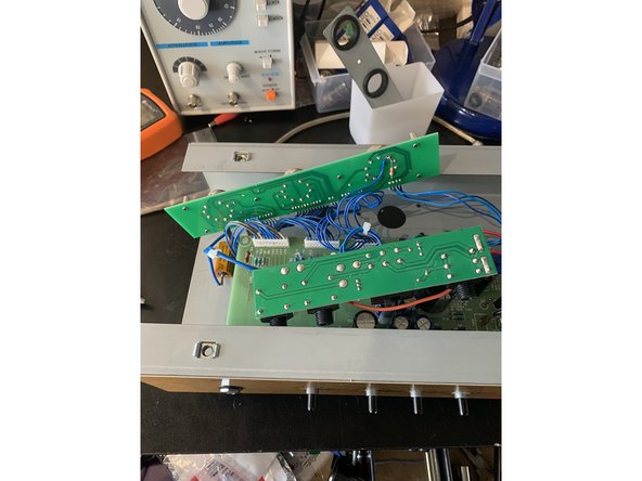
Gently push in and lift out the jacks PCB
-
With the jacks PCB pushed out of the way gently pull the tube PCB up
-
-
-
DO NOT DO THIS STEP IF YOUR CLASS 5 HAS THE TUBE SOCKETS ON THE MAIN PCB
-
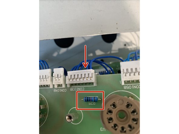
Looking at the tube socket side of the board clip the wire three connections to the right on connector CON103B. Be sure to clip it as flush to the connector as you can.
-
Remove the solder from pins 6 and 9 on V3. Strip and tin the end of the wire you clipped from CON103B. Solder the wire and one end of the 100 ohm 1W resistor to pin 6 and the other lead of the resistor to pin 9. Leave about 1/8" clearance above the PCB for the resistor
-
With the solder removed from the pins you should be able to insert the wires into the holes with the pin connections before soldering. Make sure the leads are not toucing any other pins!
-
Re-install the tube PCB
-
-
-
Remove R25 and replace with a 10k 1/2W resistor. If your Class 5 has a separate Tube PCB R25 will be on there, if not then it is on the main PCB next to the EL84 pins.
-
-
-
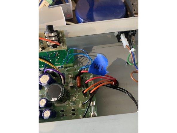
Disconnect: W1, W2, W3, W4. use a low tack tape and a sharpie to mark their locations so you can put them back in the right places
-
Remove the knobs, nuts, and washers from the pots
-
Remove the nut and isolation washer from the input jack. There is a second isolation washer on the other side of the jack, it doesn't need to be removed, but don't lose it!
-
Remove the screws at either corner of the PCB near the output PCB and Tube PCB and the screw and lock washer near the center of the board
-
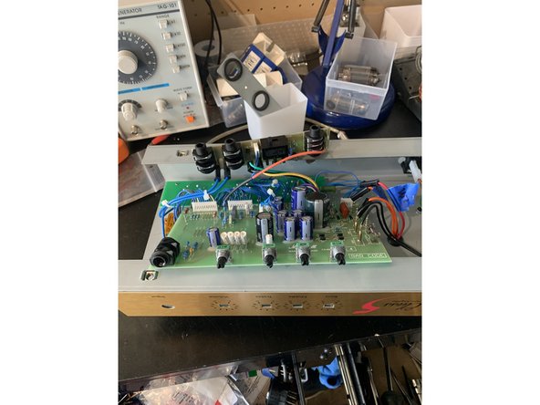
The main PCB should now be loose. Holding only the sides of the PCB and with the output PCB up and out of the way push it towards the back of the chassis until the pots will clear the chassis then lift the front of the PCB up until it clears the chassis. It's a fairly tight fit so be careful and don't force it!
-
-
-
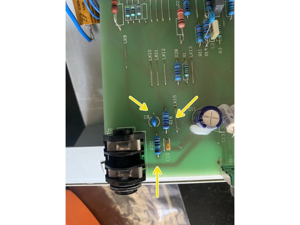
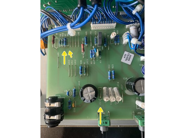
Remove R20, R18, and C8
-
Install 1M resistor in R20, 2.7k resistor in R18, and 1uf cap in C8
-
-
-
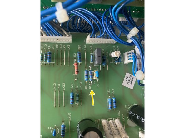
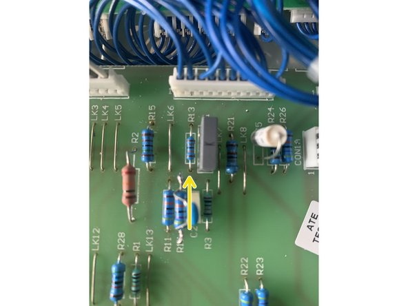
Remove R7, R9, and C13
-
Install 470k 1/2w resistor in R7
-
Using a lead clipped off of a part you used to jumper where C13 used to be
-
R9 should be empty
-
-
-
Remove R28, C14, C20, and C21
-
Install 56k in R28
-
Install .022uf Mallory 150 in C20 and C21
-
Install 270pf in C14
-
-
-
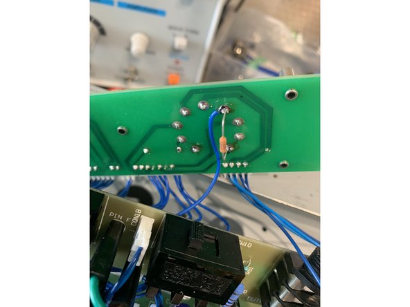
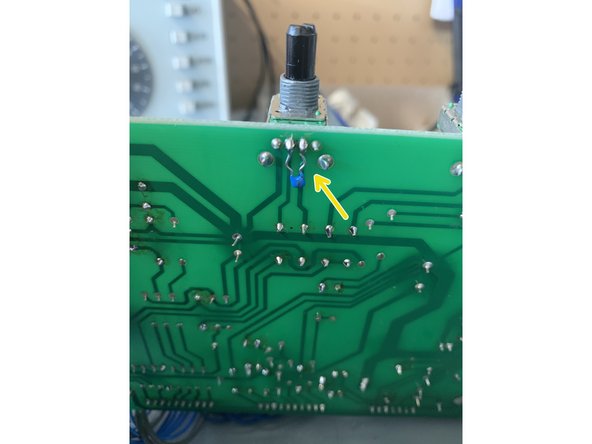
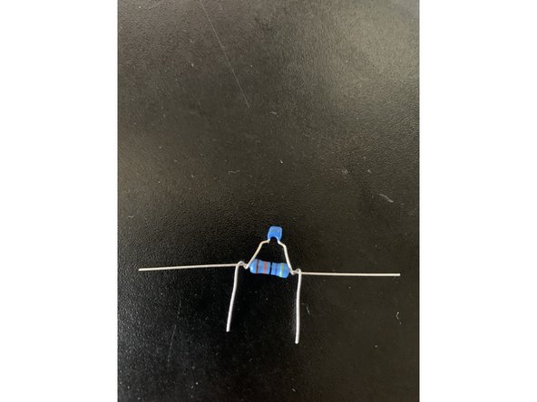
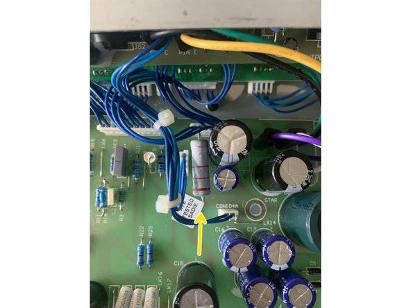
Remove R14
-
Twist the 470pf leads around the 470k resistor as shown in the pic and solder. Clip the hanging leads off and install in R14.
-
-
-
Remove R27 and replace with 220 ohm 3W resistor
-
Make sure this resistor is mounted 1/2" off of the PCB and isn't touching any of the nearby components
-
-
-
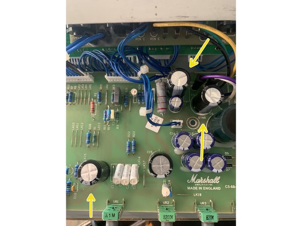
Remove C3, C4, and C11
-
Install 22uf/ 400v caps in C11 and C3
-
Install 100uf/ 400v cap in C4
-
-
-
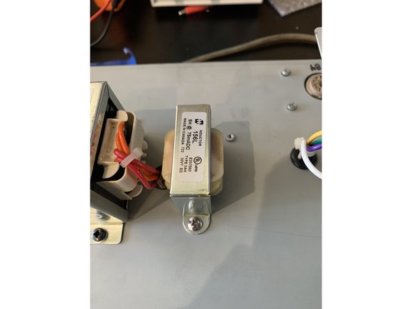
Carefully mark and drill 3/16" holes for mounting the choke next to the inlet grommet for the power transformer.
-
Using an automatic center punch to mark the drill holes is a great way to keep your drill bit from "walking" when using a hand drill.
-
Be very careful to not drill into the PCB when using a hand drill!
-
Mount the choke using the supplied 1/2" 8-32 bolt and keps nut.
-
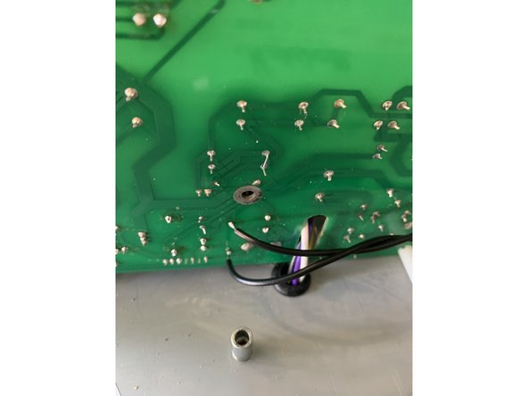
Twist and tin the choke leads
-
Remove R5 and install the choke leads in each of the holes where R5 was.
-
I like to twist the choke leads and run them under the PCB inserting the leads from the bottom of the PCB and soldering there as well.
-
-
-
Carefully put the main PCB back in. Install the nut and washer on the input jack. Put the screw back in near the middle of the PCB and at either corner. Install washers, nuts, and knobs on the pots.
-
Put the output PCB back in and attach the three plastic nuts, two red and two black.
-
Flip the amp over and Re-install the tube pcb: 4 screws and 2 standoffs. Mount the tube guard on the standoffs and screw the two screws in.
-
Put the tubes in
-
Put the chassis back in the cab, screw the four screws in, and you are Ready to rock!
-


One Comment
Hi,
I've made the modifications, but I find there's far too much treble (especially with an overdrive pedal). I removed the 470pF capacitor from resistor R14, which is fine, but the sound becomes quite flat, with less gain and volume. Do you have any suggestions for taming these harsh highs? Thank you very much!