
-
-
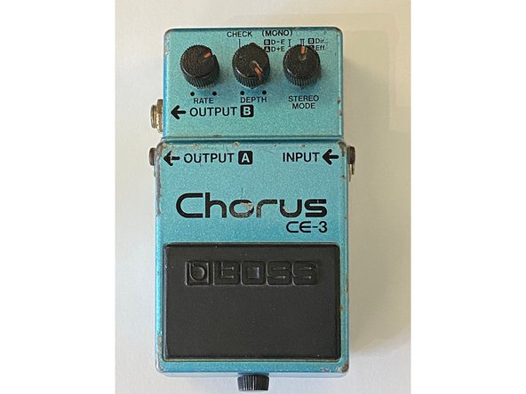
Make sure this is the guide for your pedal!!!
-
Remove the 4 screws holding the back panel.
-
Set aside the 4 screws and the clear plastic shield
-
-
-
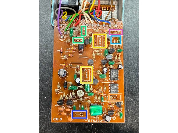
Remove the highlighted components.
-
This is what the solder side should look like after removal of the parts.
-
-
-
1uf MLCC
-
473 MLCC
-
474 MLCC
-
Op Amp - note orientation
-
75pf MLCC
-
470k Resistor
-
-
-
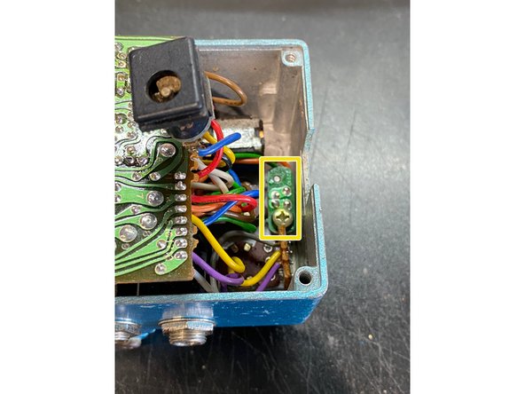
Remove the LED circuit board
-
re-use the LED spacer and the short lead will go to the same pad the greed wire is soldered to.
-
Mind your polarity, long lead is positive and short lead is negative.
-
-
-
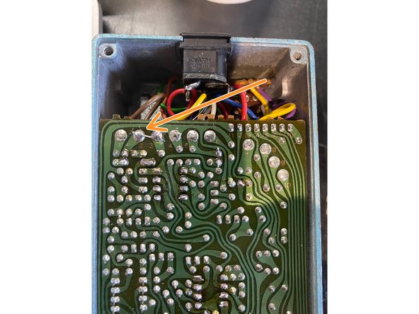
To convert to PSA power bridge pins 2 and 3.
-
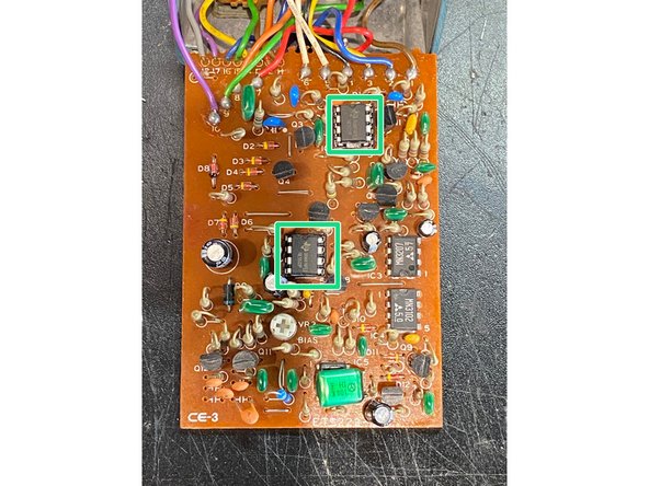
Insert the new Op-Amps.
-
Note the orientation of the op-amps.
-
-
-
All of the caps in the kit for this step have a minimum voltage rating of 25V, but may be as high as 50V. Your pedal will still work just fine with 9V after these mods, you just won't damage it if you use up to 18V
-
Replace C15 with 10uf
-
Replace C18 with 100uf
-
Replace C27 with 47uf
-
-
-
Put the plastic shield and backplate on the pedal reversing the dis-assembly steps and you are ready to ROCK!!!
-
-
-
After swapping out the parts put your pedal back together and enjoy your new pedal!
-
Troubleshooting: Check to make sure that the soldering all looks shiny and that two pads aren't bridged by too much solder. Check to make sure no pads have lifted, if they have you can use a lead cut off a component to connect the broken connections. Check to make sure that none of the wires have come loose at the top of the PCB and fix them if so
-


2 Comments
Loving your Mods! This one looks amazing too. Can I ask, is it possible to replace the MN3207 to a MN3007 (as used in the CE-2) without serious repercussions? Cheers!
Keith Harper - Open Reply
Awesome! Sorry for the late reply, they run on different polarity so it would require an adapter PCB which we don't have any plans to make.