Tools
-
-
WARNING Performing these modifications WILL void the warranty on your amp. Working on amps can be DEADLY if you do not take proper precautions.
-
Follow these instructions very carefully. If at any point in the mod process you are at all unsure of your ability to do these mods take your amp to a professional to be modded. You can also send your amp to me to be modded.
-
No Warranty - This kit and the instructions do not include a warranty of any kind. The modifications to your amplifier are at your own risk and you agree to hold harmless the seller of this kit against any and all claims
-
Tube amps contain parts that operate at very high temperatures and deadly voltages.
-
Buy the kit here: https://fromelelectronics.com/collection...
-
-
-
Follow these instructions to the letter
-
It's a good idea to have all the parts and tools laid out before starting in a well lit area
-
Remove the tubes, unplug the speaker, unplug the reverb from the chassis( be sure to not which side is red and which side is white). Remove the clips holding the power cable to the cabinet
-
Remove the screws holding the back panel and remove the panel.
-
The chassis should now slide out easily exposing the PCB. I find it easiest to work on the amp with the chassis completely removed from the cabinet.
-
-
-
Warning skipping this next step could result in death
-
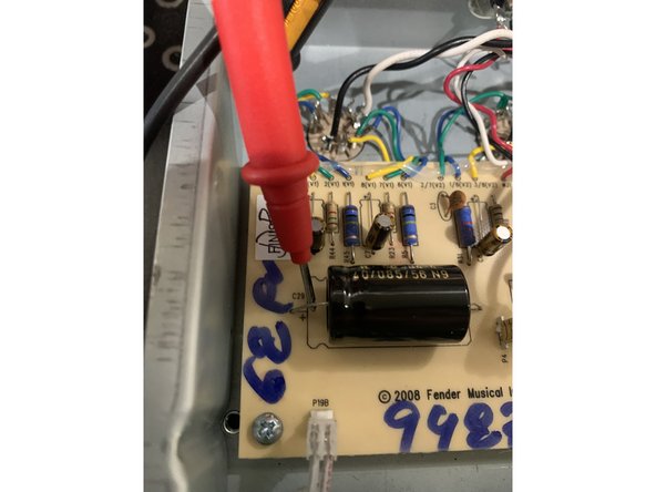
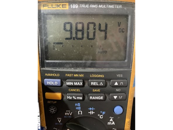
Using your multimeter set to DC measure the voltage between the positive side of C29 to ground. If the voltage is higher than 10VDC you need to drain the charge that's still in the caps
-
Use a lead with alligator clips on both sides to connect pin 3 on V1 and pin 1 on V1, leave it connected until the voltage at the filter caps measures under 10 volts. This will slowly and safely drain DC from the amp.
-
Keep repeating the last step until the voltage reads below 10VDC
-
-
-
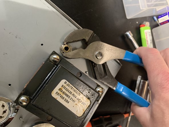
Remove the control knobs by loosening the set screws and all the nuts securing the pots and jacks to the chassis
-
Clip all the wire ties
-
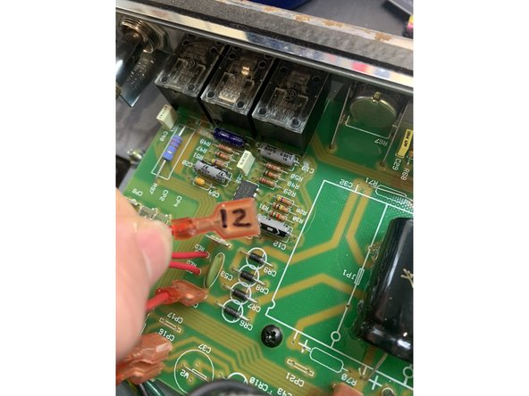
Unplug the power and output transformer's leads by pulling firmly with steady pressure while gently rocking the lead terminal from side to side. As you remove each lead tag the wire with the number off the terminal connection it was removed from. You can either use masking tape and a Sharpie or I just mark the terminal number on the lead
-
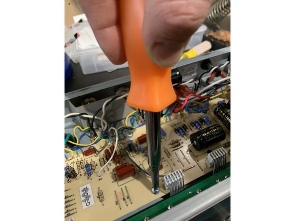
Remove all the screws holding the PCB to the chassis
-
-
-
Pull gently on the main PCB to make sure it's not stuck to any of the standoffs that were folding the pcb screws
-
Disconnect the bias pot from the bottom side of the chassis
-
Disconnect the grounding lug screw near the pilot light.
-
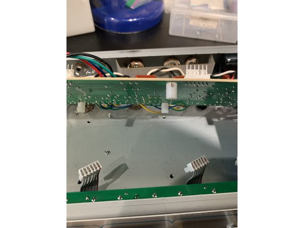
Disconnect the ribbon cables between the main PCB and the control panel PCB
-
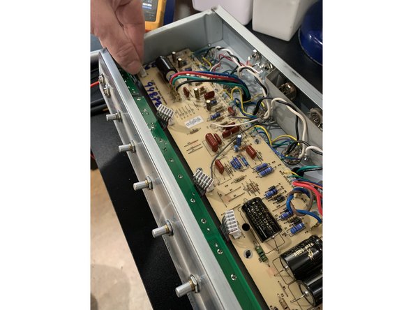
With the main PCB screws removed pull it up and back carefully, being mindfull of the wires running from the PCB to the tube sockets. You'll need to have the control panel side of the main PCB pulled up from the chassis to access the solder side of the main PCB
-
With the knobs, all nuts, and washers removed removed the control panel pcb should pull freely away from the front of the chassis and be removed
-
Do not put any pressure on any components, including the filter caps, while moving the PCBs
-
-
-
Be careful that your soldering iron isn't too hot. The solder pads and circuit traces on the PCBs are fragile and prone to curling and separating from the PCB.
-
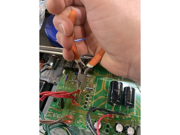
Remove components with care, never using force. It's best to clip the component leads flush to the board on the component side and then remove the remainder of the lead and solder from the solder side with de-soldering braid.
-
If a pad comes off during de-soldering carefully scrape the trace next to the pad to expose the copper, bend the lead so it's in contact with the exposed copper trace, and solder them together.
-
-
-
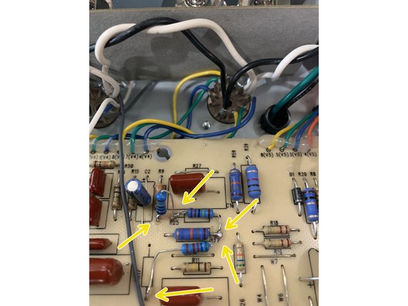
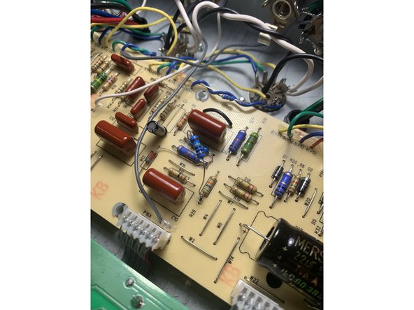
On the main PCB remove R25, R17, and R27
-
Solder one side of the 1M resistor to the bottom hole of R9 and the other to R25
-
Couple one lead of the 2.2M resistor to the 1M resistor that's going into the hole on the left side of R25 and couple the other lead to the right side of R57
-
Also couple one lead of the 56K resistor to the right side of R57 as well with the other lead of the 56k resistor going to the bottom hole of R17
-
Jumper R27 with a lead from a clipped component
-
This mod moves the phase inverter's power supply to an unused higher voltage power supply increasing clarity, clean headroom, and tone! It also grid biases the phase inverter to prevent the harsh doubling distortion it has stock when it starts to break up.
-
-
-
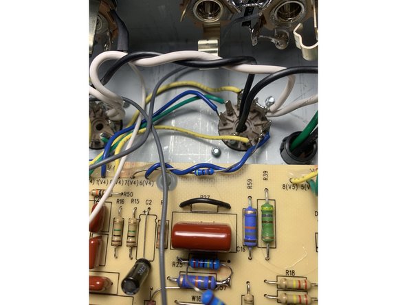
On the main PCB remove R25, R17, and R27
-
Solder one lead of the 2.2M resistor to the hole on the left side of R25 and couple the other lead to the right side of R57
-
Also couple one lead of the 56K resistor to the right side of R57 as well with the other lead of the 56k resistor going to the bottom hole of R17
-
Solder the 1M resistor to the left side of R25 and the bottom of R26. I like to leave it a little long so there's space between this resistor and R57
-
Jumper R27 with a lead from a clipped component
-
Remove the lead going from 7(V-4) to V4 pin 7. Install 470k resistor from 7(V-4) to pin 7. Desolder the blue lead from pin 6 of V4. Wrap the blue lead around the 470k resistor and re-solder to pin 6. Make sure the 470k resistor isn't touching the standoff screw or any other tube pins!
-
This mod moves the phase inverter's power supply to an unused higher voltage power supply increasing clarity, clean headroom, and tone! It also grid biases the phase inverter to prevent the harsh doubling distortion it has stock when it starts to break up. We also add a grid resistor to further smooth out the phase inverter as it's driven.
-
The difference between this and earlier versions is that we change where the phase inverter grid resistor is grounding because we change the grounding scheme in this version of the kit in later steps.
-
-
-
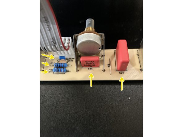
On the control Panel PCB remove: R52, R46, C19, C23 and C24
-
On the control panel board install: 10K in R52, 91K in R46, 270pf MLCC in C19, .047 in C23, and .1 in C24
-
-
-
Only follow this step if you have the Supreme kit. Save the leads from the filter caps - you'll be using them for the next step.
-
The electrolytic caps in this step are polarized, meaning they will only work in a circuit connected with their negative and positive leads connected to the corresponding negative and positive connection in the circuit. The PCB is marked with a "+" sign closest to the positive connection for the cap.
-
If polarized caps are incorrectly installed they can explode
-
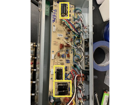
Remove the filter caps: C29, C27, C26, and C28
-
Remove C1, C2, C7, C8, C9, and C18
-
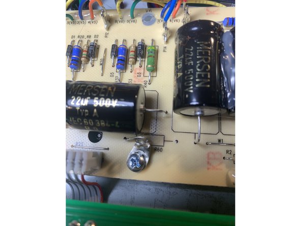
Install 22uf/ 500V filter caps in C26, C27, C28, and C29
-
Install 22uf/ 35V caps in C1, C2, C7, C8, C9, and C18
-
The voltage rating on caps for C1, C2, C7, C8, C9, and C18 in the kits can be anywhere from 25V to 63V for this part depending on our supplier. This voltage rating is a maximum working voltage and for where they are used in the circuit they will see less than 10V.
-
-
-
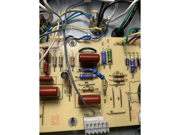
This step will change the grounding to be more like a vintage amp and lower the noise floor of your amp.
-
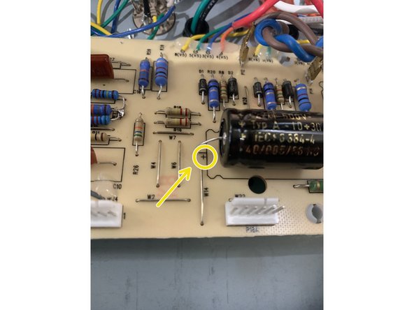
Remove R60( and the solder from the hole on the left side) and install a solder lug in the standoff screw next to R60. Using a lead clipped from the filter caps solder one end to the solder lug and the other to the left hole of R60 - see photo. It's easier to attach the lug to the screw before soldering the R60 hole.
-
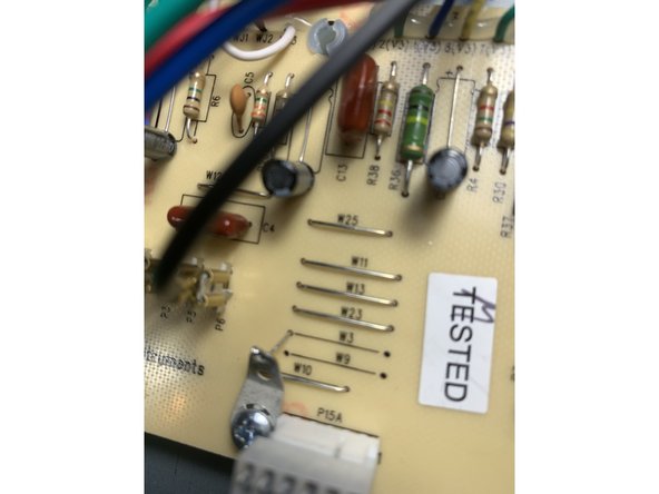
Remove Jumpers W3 & W9( and the solder from the left side of W3). Install a solder lug in the standoff screw next to the control pcb header. Using a lead clipped from the filter caps solder one end to the solder lug and the other to the left side of W3 - see photo
-
If you have an earlier version of the kit you're welcome to do this( and I recommend it), but your kit won't have the solder lugs or resistors in step 8.
-
-
-
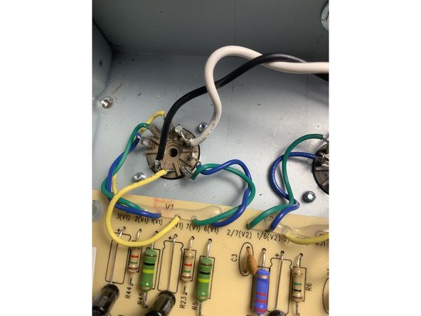
De-solder the blue wire from V1 pin 1. Wrap it around the green wire going to pin 2 and re-solder blue wire at pin 1.
-
De-solder the blue wire from V1 pin 6. Wrap it around the green wire going to pin 7 and re-solder the blue wire at pin 6.
-
De-solder the blue wire going to V3 pin 6. Wrap it around the green wire going to pin 7 and re-solder the blue wire at pin 6.
-
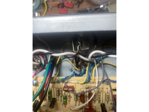
Push all of the wires running from the PCB to the tube sockets, especially the blue and green pairs, close to the chassis and away from the black and white heater filament wires that run above the tubes. At V1 and V2 I like to push the heater wires towards the back of the chassis as well.
-
-
-
Carefully put the control panel PCB back into the front of the chassis solder side up and fasten the washers and nuts onto the pots
-
Carefully put the main PCB back into the chassis and screw it back into the standoffs.
-
Reconnect the ribbon cables being mindful that they are properly aligned to the pins coming off the main PCB
-
Make sure the ribbon cables have a smooth path and don't have any kinks or sharp turns in the cabling
-
Reinstall the bias pot with the nut on the bottom of the chassis next to the power transformer
-
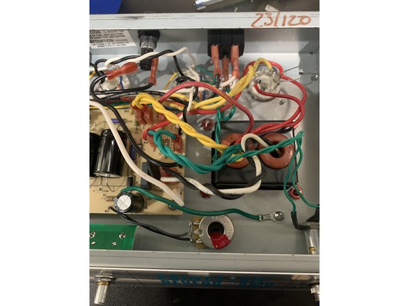
Dress the transformer leads. Poor lead dress is one of the main causes of noise in this amp. Instead of using new cable ties we're going to use proper lead dress techniques
-
Twist each pair of AC leads from the transformers: yellow, green, and black and white together. All leads and twisted pairs if possible should cross each other at 90 degree angles
-
Slide the chassis back into the cabinet from the back of the cabinet and secure the chassis with the two top screws
-
-
-
Plug the speaker into the speaker jack
-
Re-install the control knobs
-
Enjoy your new amp!
-