
Introduction
Thanks for purchasing the Pro Jr. Modification Kit. After these simple changes, your amp will sound so much better. Please read through this entire guide prior to starting the mod. If you have any questions please let us know.
This is an interactive guide and we encourage you to leave comments (good and bad) as well as any tips or tricks you have that may help everyone!!!
Words of Caution:
If your amp is currently under factory warranty performing these mods will void it.
We guarantee the quality of components and completeness of the kit. However, we cannot guarantee the quality of your work. We are always happy to help troubleshoot via email support.
Tube amps operate at very high temperatures and deadly voltages. Special care must be taken when working on an amp. Wear Safety Goggles at all times, make sure filter caps are drained, only use tools with insulated handles, wear rubber-soled shoes. Finally any time the amp is plugged in keep your left hand in your pocket and only work with your right hand.
If you are unsure of your ability to perform these mods get some help!!! Feel free to reach out to us with any questions if you are on the fence. A qualified local tech should be able to do the mods in 2-3 hours. We also offer installation service for this kit if you want to send the amp into our shop, we charge 2 hours of labor ($200) plus actual shipping both ways.
Optional Tool/Supplies:
Silicone Glue/Caulk
9/16” nut driver or socket wrench
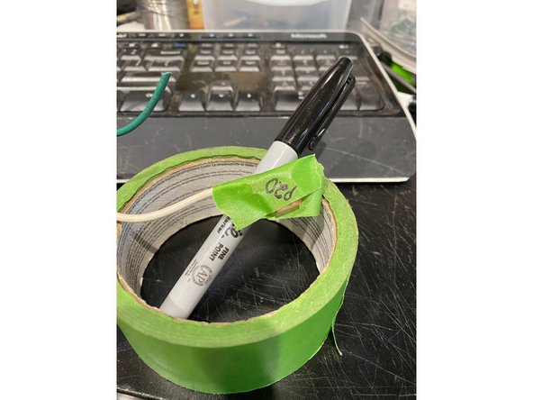
Fine point sharpie
Masking Tape
Tools
Parts
- 100 Ohm 1/2 Watt Resistor
- 10k 1/2 Watt Resistor
- 20k 1/2 Watt Resistor
- 22k 1/2 Watt Resistor
- 56k 1/2 Watt Resistor
- 82k 1/2 Watt Resistor × 2
- 100k 1/2 Watt Resistor × 2
- 470k 1/2 Watt Resistor
- 1m 1/2 Watt Resistor
- MLCC 100p Cap
- Wima 4700pf 7.5mm
- Wima .015 7.5mm Cap
- 100uf or 80uf high voltage cap
- 22uf or 20uf high voltage cap × 2
- 22uf cap low voltage
- 3 inch stranded tinned wire × 2
- Wima .022 10mm Cap
- Fromel input jack PCB
-
-
It’s a good idea to have all the parts and tools you will need to be laid out before starting in a well-lit area.
-
Unplug the Amp and put on your safety goggles.
-
Remove the chicken head control knobs (they pull off) and the nut holding the input jack with a 9/16” nut driver or socket wrench.
-
Remove the 6 screws holding on the back panel and remove the panel. If the back panel does not come off easily you can loosen the two chassis screws on the side of the amp about a half turn each.
-
-
-
Drain the Filter Caps: The filter caps on your amp may be drained already but you must follow these steps to ensure that any deadly voltage is removed from the amp before you begin work.
-
Test the voltage across the filter caps. Set your multimeter to DC and measure the voltage across the positive and negative sides of any of the filter caps. If the voltage reads higher than 10 VDC, then you need to drain the caps.
-
Use a lead with alligator clips on both sides to connect pin 3 on V1 and pin 1 on V1, leave it connected until the voltage at the filter caps measures under 10 volts. This will slowly and safely drain DC from the amp.
-
-
-
Clip all of the Zip ties (all of them). When putting the amp back together we will be re-routing most of the wires for proper lead dress.
-
Unplug all the transformer leads by pulling firmly with steady pressure gently rocking the lead terminal from side to side.
-
As you remove each lead mark the wire with masking tape and a Sharpie so you will know where to plug it back in when you are putting the amp back together. I write the terminal number on the lead.
-
-
-
The solder pads on the PCB are prone to curling and separating from the PCB, remove the components with care, never heat the solder and pull the component out you will take the trace with it! We recommend using de-soldering braid as solder suckers can rip the pads off the PCB.
-
For axial components (leads on each side), it is best to clip the leads on the front of the PCB then remove the remainder of the lead and solder from the backside carefully with de-soldering braid. For radial components (both leads on bottom) it is best to remove the solder first.
-
-
-
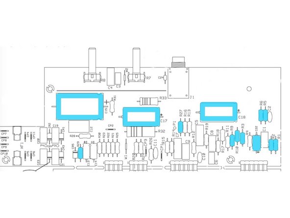
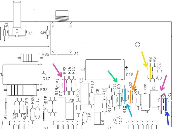
Clip the leads and remove the axial mount components noted below and highlighted in Blue. The large filter caps may be glued down with silicone. After the lead is clipped, using pliers gently twist the cap off the board.
-
RESISTORS: R1 - R2 - R3 - R5 - R6 - R9 - R10 - R27 - R29( If you have the newest version Pro Jr IV with a black circuit board DO NOT remove R29! - it doesn't get swapped). Pro Jr IV's and some III's don't use the same volume control circuit and don't have an R6 so you don't have to worry about that.
-
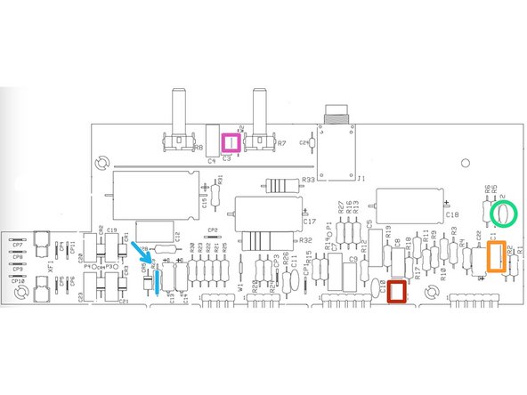
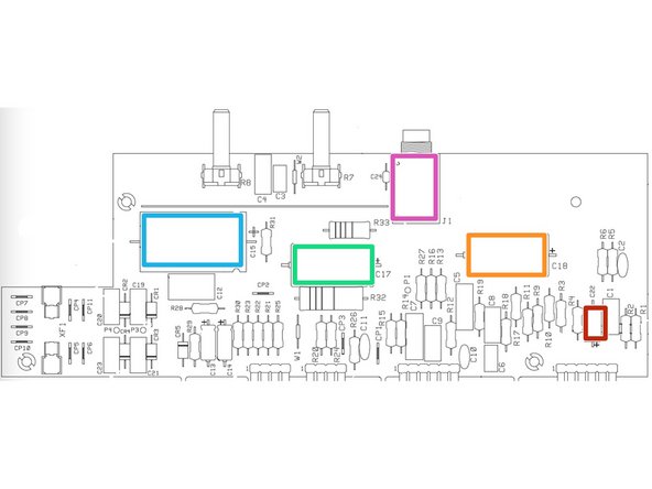
SUPREME KIT ONLY: CAPACITORS: C15 - (C16 If present) - C17 - C18 - C22 (some versions may say C23. Some early versions of the Pro Jr don't have a C22 or C23 so you won't be removing it.
-
NOTE: Early versions of the Pro Jr have two 22uf filter caps at C15 and C16, for amps with caps in C15 and C16 you will remove both C15 & C16 and then install a cap in C15 and leave C16 empty. Later versions have a single 47uf cap at C15.
-
-
-
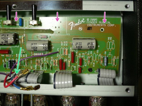
Pull gently on the board to make sure that it is not stuck to any of the standoffs that were holding the circuit board screws.
-
Press the wires from the output transformer as far away from the board and as close to the chassis as possible. The board needs to come down toward the bottom of the amp before the pots will clear the top of the chassis as shown.
-
Using gentle pressure on the top of the circuit board press the board down making sure it is not getting hung up on any wires until the pots have cleared the top of the chassis then pull the board to you to expose the underside.
-
DO NOT PUT PRESSURE ON ANY COMPONENTS INCLUDING THE FILTER CAPS WHEN MOVING THE BOARD.
-
-
-
Use de-soldering braid to carefully remove the solder joint and remaining lead on all the components you removed in the previous step (highlighted in blue)
-
If you have the newest version Pro Jr IV with a black circuit board do not remove R29!
-
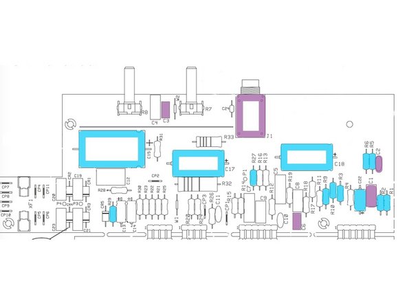
De-solder the following components highlighted in purple. C1 - C2 - C3 - C6 - Input Jack. Pro Jr IV's and some II's don't have a C2, if you don't have it don't worry about it. If your later Pro Jr has a 500pf C3 do not remove C3, remove C4 instead.
-
Do not use force to remove a component! De-soldering braid is your friend, solder suckers are an enemy. On the input jack it may help to de-solder, clip the pins flush with the board, and de-solder again.
-
-
-
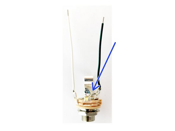
Follow this step if your kit came with open frame jacks
-
Solder the wires included in the kit to the jack as shown. The ground wire should bridge the ground and middle( switch) lugs.
-
Solder the jack wires to the PCB with the ground/ switch connection closest to the top of the board( control side) and the tip wire closest to the bottom( tube side)
-
-
-
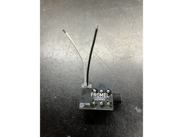
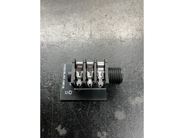
If your kit came with the Fromel input jack PCB follow the instructions below
-
Remove input jack. This part is snapped into the PCB and then soldered. I find it's easiest to remove the solder from the back side first and then remove the jack.
-
Solder the jack to the jack PCB oriented as shown in the photo
-
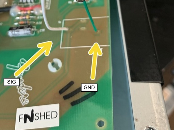
Attach leads to the jack PCB at SIG and GND
-
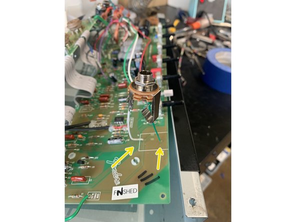
Connect the leads from the jack PCB to the Pro Jr main PCB at the points shown in the photo
-
-
-
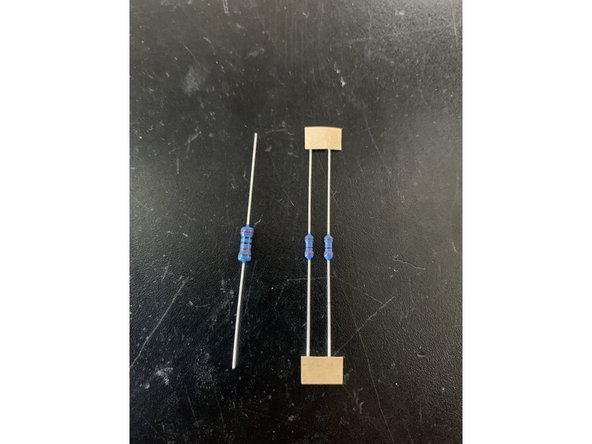
Some of the resistors in this kit may be a different size than others. Specifically some of the 1/2W resistors may be a smaller size, depending on what our suppliers have available. We assure you these are indeed 1/2W resistors
-
For caps high voltage means anything above 400v and low voltage means anything under 100v. The high voltage caps will be in an axial package
-
-
-
Insert all the components to the top side of the board before soldering. This prevents repeated bending of the ribbon cables which can cause them to break.
-
R1 = 10K
-
R2 = 1M
-
R3 = 100K
-
R6 - This resistor controls the overall gain (breakup). For more clean headroom install the 22k, for earlier breakup (more gain) install the 82k. To keep the gain structure the same install the 56k. Pro Jr IV's and some III's don't use the same volume control circuit and don't have an R6
-
R9 = 100 Ohm
-
R10 = 100k
-
R27 = 82k
-
-
-
R5 - 470K
-
R29 = 20k ( If you have the newest version Pro Jr IV with a black circuit board do not change R29)
-
C1 = Wima 10mm .022 Cap
-
C2 = 100pf MLCC (the little blue one). Pro Jr IV's and some II's don't have a C2, if you don't have it don't worry about it.
-
C3 or C4( depending on which version of the amp you have) = Wima 7.5mm 4700pf cap
-
C6 = Wima 7.5mm .015 Cap
-
-
-
The following parts are polarized and must be inserted correctly. Positive to positive, negative to negative. On axial caps the dent indicates the positive side. On radial caps the positive lead is longer and the negative side has a black stripe. The PCB has indicators for +.
-
C23 or C22 = 22uf low voltage radial cap. Depending on the version you have this may say C23 or C22.
-
C15 = 100uf or 80uf high voltage cap
-
C17 = 22uf or 20uf high voltage cap
-
C18 = 22uf or 20uf high voltage cap
-
Install input jack, the ground or GND wire goes in the hole closest to the top of the board and the tip or SIG goes to the hole closest to the tubes.
-
NOTE: Early versions of the Pro Jr have two 22uf filter caps at C15 and C16, for amps with caps in C15 and C16 you will remove both C15 & C16 and then install a cap in C15 and leave C16 empty. Later versions have a single 47uf cap at C15.
-
-
-
Carefully put the PCB back into place making sure that the pots and input jack all line up with the control panel.
-
Replace all of the PCB mounting screws
-
Make sure all the ribbon cables have a smooth path with no kinks or sharp turns in the cable
-
-
-
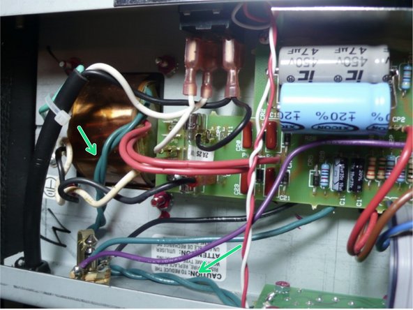
Proper lead dress is critical to reducing noise and oscillation in an amp. AC lines carry 60 cycle hum. This is reduced when the lead pairs are twisted together creating a shield. Avoid running lead pairs parallel to each other, if possible lines should cross at a 90 degree angle.
-
The most important leads to twist are the Green heater wires. Also twist the red pair from the power transformer to the PCB (opposite of what you see in the pic.)
-
Plug the speaker back into the speaker jack
-
-
-
Re-install the control knobs and install the jack with the isolation washers and nut.
-
Replace the back panel and make sure to tighten the chassis screws on the sides if you loosened them. The silver screw is for the top center back panel screw. It's just a bit shorter than the stock screws and will reduce hum in early models of the Pro Jr
-
Enjoy your modded amp!
-


Cancel: I did not complete this guide.
One other person completed this guide.

One Comment
While you've got the amp undressed, replace the crap stock speaker. You won't believe how good this amp sounds until you put a decent speaker in it.
Lee Downey - Resolved on Release Reply