Introduction
Thanks for purchasing the Pro Jr. Supreme Tube Board. If you are reading these instructions and don't have the kit you can order it here.
Please read through this entire guide prior to starting the mod. If you have any questions please let us know.
This is an interactive guide and we encourage you to leave comments (good and bad) as well as any tips or tricks you have that may help everyone!!!
Words of Caution:
If your amp is currently under factory warranty performing these mods will void it.
We guarantee the quality of components and completeness of the kit. However, we cannot guarantee the quality of your work. We are always happy to help troubleshoot via email support.
Tube amps operate at very high temperatures and deadly voltages. Special care must be taken when working on an amp. Wear Safety Goggles at all times, make sure filter caps are drained, only use tools with insulated handles, wear rubber-soled shoes. Finally any time the amp is plugged in keep your left hand in your pocket and only work with your right hand.
If you are unsure of your ability to perform these mods get some help!!! Feel free to reach out to us with any questions if you are on the fence. A qualified local tech should be able to do the mods in 2-3 hours. We also offer installation service for this kit if you want to send the amp into our shop, we charge 2 hours of labor ($200) plus actual shipping both ways.
Optional Tool/Supplies:
9/16” nut driver or socket wrench
Fine point sharpie
Masking Tape
Tools
No tools specified.
-
-
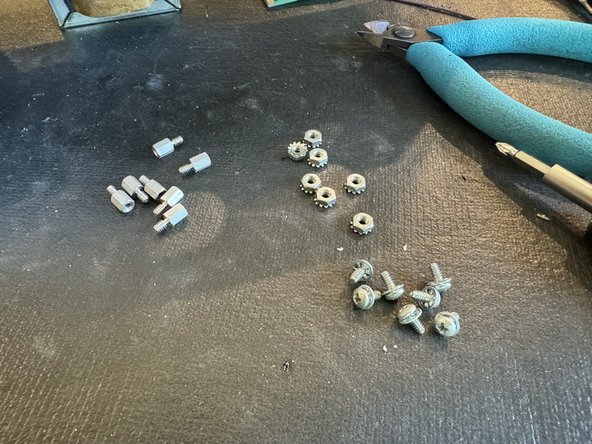
It’s a good idea to have all the parts and tools you will need to be laid out before starting in a well-lit area.
-
Unplug the Amp and put on your safety goggles.
-
Remove the chicken head control knobs (they pull off) and the nut holding the input jack with a 9/16” nut driver or socket wrench.
-
Remove the 6 screws holding on the back panel and remove the panel. If the back panel does not come off easily you can loosen the two chassis screws on the side of the amp about a half turn each.
-
Check to see if there is no DC voltage on the filter caps. See Step 2 of Pro Jr Supreme Mod kit ( JUNE 2022) and follow directions for safely draining voltage from the amp before working on it.
-
Unplug the speaker cable. Remove the screws holding the chassis and remove the chassis from the cab.
-
-
-
Unscrew the 7 screws holding the tube board and pull it free of the chassis( see pic)
-
Remove P5, P6, and the red and white wires going to the indicator light from the stock tube pcb.
-
-
-
DO NOT REUSE THE RIBBON CABLE! It will not work with the new tube board. We provide instructions for replacing it.
-
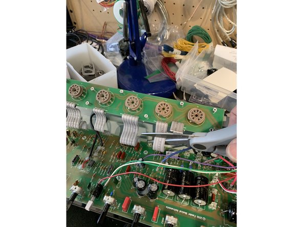
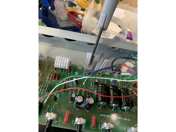
Clip all of the ribbon cables in half, then on the main PCB cut them lengthwise all the way to the PCB separating them into two leads. Clip the ribbon cable leads extending past the pad on the solder side and add some leaded solder to the pads- makes it easier to remove without damage.
-
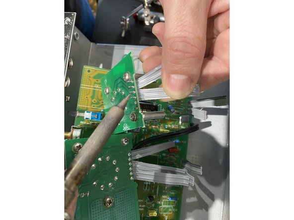
Gently tug on one of the separated ribbon cables while rocking back and forth and heating the solder connection with your soldering iron.
-
Remove all of the solder from the pads on the main PCB
-
-
-
Remove the standoffs and screws from the stock tube pcb and install the standoffs on the new tube PCB board with the fat mounting side on the tube socket side of the new pcb
-
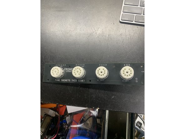
Solder the new sockets to the PCB. Make sure you're installing them on the correct side!
-
When mounting the new tube board back in the chassis leave the nut off of the stand off back between V2 and V3. Tye teeth can short the tube PCB. See photo.
-
-
-
If you have a fixed bias Pro Jr- Pro Jr I, II, III, IV( v1) remove C13, C14, and R30. Jumper C14. See pic.
-
If you have a cathode biased Pro Jr. - Pro Jr IV with a black PCB remove R39 and R40. Jumper R39.
-
-
-
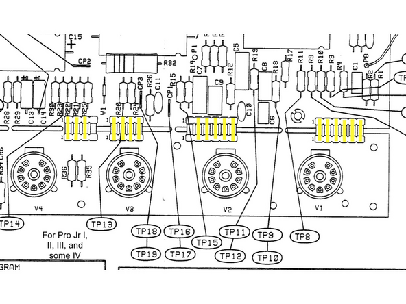
Depending on which version of Pro Jr you have you will need to wire the connections from the main pcb to the tube pcb differently. See the pics for your version of the amp.Wiring connections from main PCB to tube pcb are in yellow on the diagram. The diagram is oriented looking from the tube socket side of the chassis.
-
There are two different ways of wiring for the Fromel tube board: for the newest Pro Jr IV with a black PCB and every other version of Pro Jr. Only use the wiring diagram pic that is for the amp you have.
-
All of this info is also printed on the PCB
-
-
-
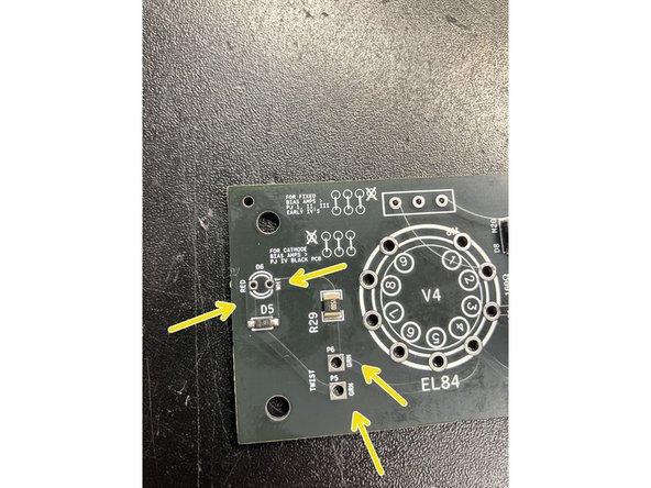
Twist the green wires removed from P5 and P6 on the old board and solder to the new tube pcb near the EL84 sockets. For P5 and P6 either wire can go in either hole.
-
Solder the red and white indicator light wires to the holes marked red and white. These must go in the correct hole or the light will not work.
-
-
-
That's all for installing the new Tube PCB. Follow the steps in the Supreme mods directions to put your amp back together and enjoy great tone!
-


