Tools
- Soldering Iron
- Solder
- De-Soldering Braid
- Multi Meter
- Phillips Screwdriver
- Pliers w/ Insulated Handle
- Wire Clippers
- Safety Goggles
- Alligator Leads
- OPTIONAL: 1/2" Nut Driver or Socket Wrench
- OPTIONAL: 9/16" Nut Driver or Socket Wrench
- OPTIONAL: Masking Tape
- OPTIONAL: Fine point Sharpie or similiar permanent marker
-
-
Remove ALL 16 screws holding the back panel on the amp.
-
Set aside the back.
-
-
-
The filter caps may be drained already but you must insure that any deadly voltage is removed from the amp before you begin.
-
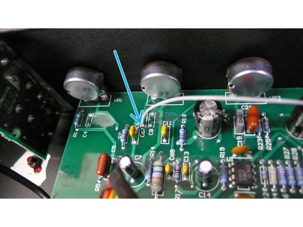
Clip one lead from your multi-meter to ground on the chassis ground and with your meter set to Volts DC, measure from the point indicated by the arrow in the picture. If the voltage is above 10 volts you must drain the filter caps.
-
Using an alligator clip, attach one side of the 330 ohm power resistor to the chassis ground and using insulated pliers to hold the 330 ohm power resistor, touch one lead of the resistor to the point indicated in the photo above. Leave the leads in contact for 30 seconds and measure again. Keep repeating this step until the voltage reads below 1
-
Capacitors can recharge even when the amp is not plugged in. After the filter caps are drained, take an alligator lead and clip one end to chassis ground and remove the red lead just above the place where you measured the voltage. Clip the other side of that alligator lead to that spade. This will prevent the filter caps from recharging.
-
-
-
We are going to be removing 3 capacitors from the circuit board. They are C4, C8 and C67. You can just clip C4 and C8, as those holes are not going to be used for anything.
-
When you remove C67 clip the side that is closest to the pots, then carefully heat the solder pad indicated with the arrow while gently pulling the component out of the hole. Then clean up the hole using de-soldering braid and/or the solder sucker.
-
-
-
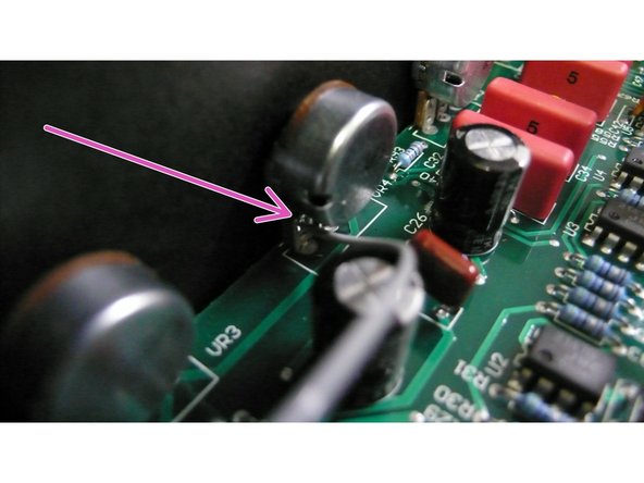
At the bass pot there is a small hole right where the pink arrow is pointing. Insert one end of the 10” wire into the hole and carefully solder it in place.
-
Take the other end of the wire and insert it into C67 as indicated in the photo above. Because the circuit board is double sided, you can solder directly from the top side of the board.
-
-
-
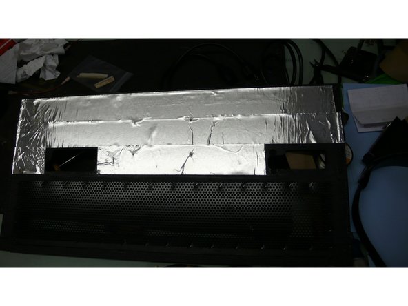
Install the shielding tape on the back panel as indicated. The tape cuts easily with scissors or an exacto knife.
-
-
-
Swap out the reverb tank.
-
The old tank indicates white for output and red for input. This is reversed on the new tank, so just make sure that the old lead for reverb input goes to the new jack for reverb input. The same goes for the output.
-
Double check all your work and put the amp back together in the same order you took it apart and you will be ready to rock!
-