
Tools
No tools specified.
Parts
- 4.7k Resistor
- 56k 1/2 Watt Resistor × 2
- 82k 1/2 Watt Resistor
- 100k 1/2 Watt Resistor × 7
- 220k 1/2 Watt Resistor
- 470k 1/2 Watt Resistor
- 680k resistor
- MLCC 100p Cap × 2
- MLCC 270p Cap
- 470pf MLCC cap × 3
- MLCC .0022uf Cap × 2
- Wima .022uf 10mm Cap × 2
- Wima .022uf 15mm
- 100k 16mm Audio Taper Pot × 3
- 3.3uf cap
- 4.7uf radial cap
- 470 ohm 5W Resistor - Hot Rod Deluxe × 2
- 330 ohm 5W Resistor - Hot Rod Deville × 2
- 100uf 450v Axial Capacitor - Hot Rod Deluxe
- 22uf/ 500v Cap - Hot Rod Deluxe Supreme only × 3
- 47uf/ 500v Cap - Hot Rod Deville Supreme only × 2
- 100uf/ 450v Cap - Hot Rod Deville Supreme Only × 2
- 22uf/ 500v Cap - Hot Rod Deville Supreme only × 2
- 80mm lead
- 120mm lead × 2
-
-
You can buy the kit from us here: https://fromelelectronics.com/collection.
-
WARNING Performing these modifications WILL void the warranty on your amp. Working on amps can be DEADLY if you do not take proper precautions.
-
Follow these instructions very carefully. I HIGHLY recommend reading through all the instructions thoroughly before you start. If at any point in the mod process you are at all unsure of your ability to do these mods take your amp to a professional to be modded. You can also send your amp chassis( and tubes!) to me to be modded.
-
No Warranty - This kit and the instructions do not include a warranty of any kind. The modifications to your amplifier are at your own risk and you agree to hold harmless the seller of this kit against any and all claims
-
Tube amps contain parts that operate at very high temperatures and deadly voltages.
-
There a couple of differences between the Hot Rod Deluxe and Deville and depending on which amp you're working on there will be different instructions you'll need to follow
-
This instruction set will not work for a Hot Rod ML, but we can do it in house. Please contact us directly if you'd like to mod your Hot Rod ML.
-
These instructions are for most versions of the Hot Rod Deluxe and Deville and are for the Supreme + Overdrive mod kit only. These mods are for BOTH the Supreme mod and the OD+ Upgrade kit for amps with previous versions of the Fromel mods. There are deviations clearly marked for OD+ Upgrade kit depending on what version of the mods you're doing.
-
-
-
Time to make sure you have the correct kit and all the parts you need to install it before getting started.
-
These instructions are for kits sold after the beginning of September 2024 and are for the Hot Rod Supreme OD+ kit only. If your kit was bought before this your instructions are here:
-
DISCONTINUED - Hot Rod Deluxe and Deville Mod Kit - April 2022 - For all Hot Rod series amps I-III
-
Now check the parts you have against the list of parts at the beginning of these instructions. If they don't match please let us know at fromelelectronics.com
-
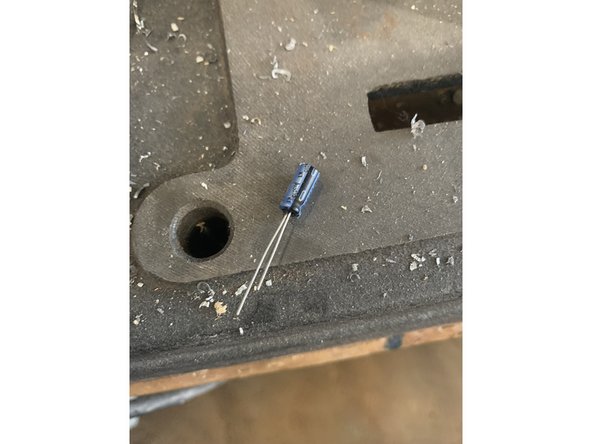
The MLCC capacitors we use have a tiny printed 3 number code to designate what they are: 101 = 100pf, 271 = 270pf, 471 = 470pf, 222 = .0022uf( 2200pf)
-
You can use the magnification on your phones photo app to see the numbers. See photo. An old fashioned magnifying glass works too!
-
-
-
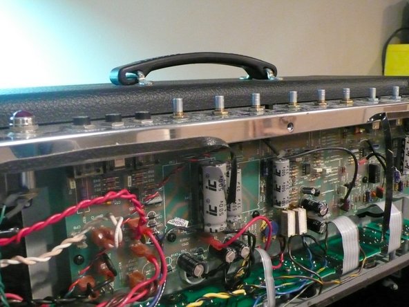
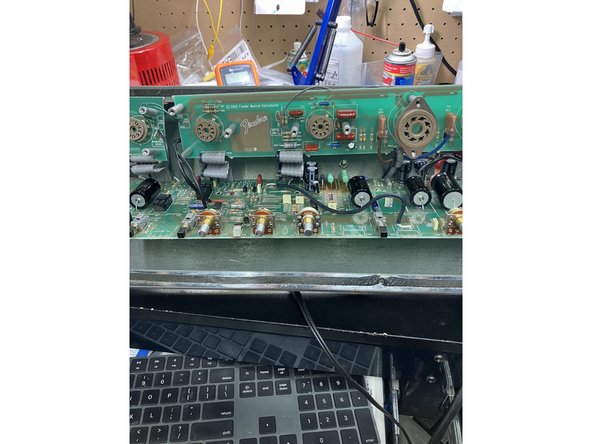
Unplug the amp and place on a level surface
-
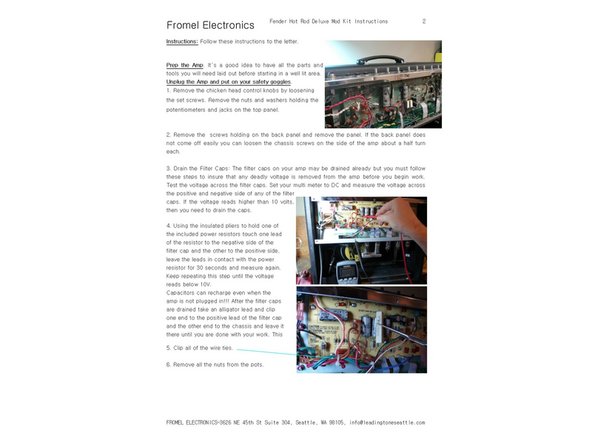
Remove the chicken head control knobs by loosening the set screws. Remove the nuts and washers holding the potentiometers and jacks on the top panel
-
Remove the screws holding on the back panel and remove the panel. If the back panel does not come off easily you can loosen the chassis screws on the side of the amp about a half turn each
-
-
-
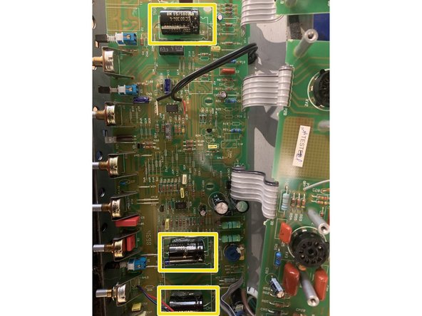
With the amp off and unplugged check to see if your caps are charged, set your multi-meter to DC and measure the voltage at the positive side of the filter cap closest to the power switch
-
If you measure more than 12VDC, you need to drain the caps. If there are less than 12VDC you may proceed to the next step
-
FAILURE TO DO THIS STEP COULD CAUSE INJURY OR DEATH BY ELECTROCUTION!
-
-
-
Remove the smaller tube PCB that supports the tube sockets: Remove the tubes and then remove the small black screws that hold both the larger tube PCB and the smaller V1 tube PCB to the chassis. Gently lift both tube PCBs free of the chassis
-
-
-
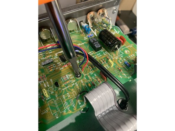
Remove all zip ties. They can be clipped off, be sure to not clip any wires or strip any insulation from the wires.
-
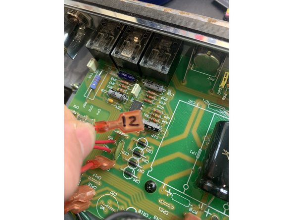
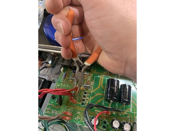
Unplug all of the quick connect leads from the choke, power, and output transformers and the switches by pulling on the quick connect firmly with steady pressure while gently rocking it from side to side. Using a pair of angled needle nosed pliers makes this much easier
-
As you remove each lead be sure to mark the terminal number on the lead with a fine point Sharpie pen so you will know where to plug it back in when the amp mods are done
-
Remove all PCB standoff screws and the solder terminal screw connecting the green ground wire from the Main Pcb near the input jacks to the chassis.
-
Remove knobs and all nuts and washers from the control panel
-
-
-
Pull gently on the PCB to make sure that it's not stuck to any of the standoffs where screws had been holding it
-
Press the wires from the output transformer and reverb as far away from the PCB and as close to the chassis as possible. The edge of the PCB will need to come down to the bottom of the amp where the tube PCB was before the pots will be able to clear the chassis
-
Using gentle pressure on the top of the board and making sure it's not getting hung up on any wires push it towards the back of the chassis( where the tube board was) until the pots have cleared the top of the chassis then pull the board up to you to expose the solder side of the board
-
DO NOT PUT ANY PRESSURE ON ANY COMPONENTS INCLUDING THE FILTER CAPS WHEN TRYING TO MOVE THE BOARD
-
-
-
If your version of the kit replaced the ribbon cables with leads you'll need to remove the wires running from the tube PCB V1/ V2 to points other than where the ribbon cables initially ran and wire the leads from the main PCB to the tube PCB the same as the amp was stock: 1:1.
-
If your amp is a 2002 or later and had shielded cable from the main PCB to the tube PCB( pre-mods) you'll need to wire PW1A and PW1B( the connections for V1) as shown in step 10 & 11 at this point.
-
Install: 130k in R18, 100k in R24, 100k in R25
-
Install j111 transistor in Q2
-
Remove the jumper between the pins for the removed K2 relay and also remove the jumper from the bottom of R18 to the top of R25, as done in the previous mod
-
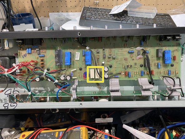
Install shielded coax cable between WJ10 - WJ11 & WJ12 - 13. Signal wire between WJ10 & 12 and shield between WJ11 & 13, just like it says on the PCB. It's a good idea to secure the coax with a zip tie at C35's ground lead. Some earlier amps don't have the 'WJ' designations - the coax
-
-
-
SKIP THIS STEP IF YOU ARE INSTALLING THE OD+ Upgrade kit
-
Remove R57 & R58
-
Install 82k 1/2W metal film resistor in R57. Install 100k 1/2W metal film resistor in R58
-
Clip the leads where they meet the PCB on the component side and then remove the solder and rest of the lead from the solder side of the PCB using de-solder braid
-
NEVER heat the solder pad and try to pull the component out it will pull the solder pad off!
-
-
-
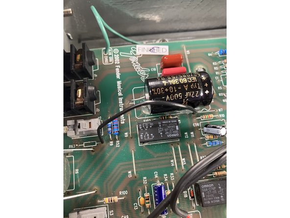
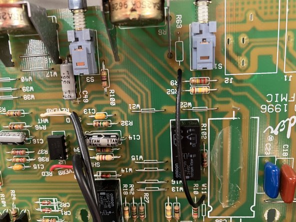
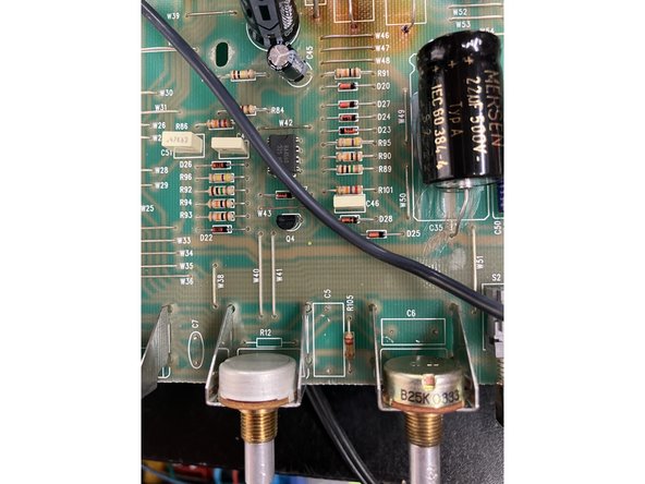
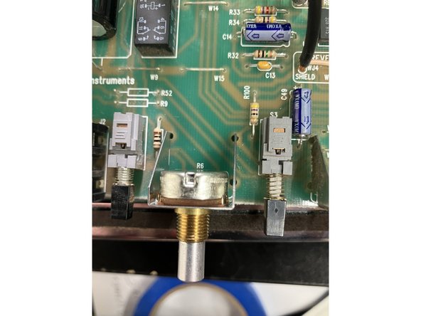
Remove Jumper W7( On older Hot Rods this is W11 - See 2nd pic) and Resistor R63
-
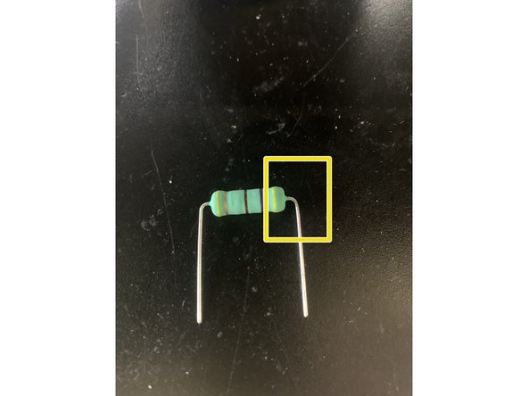
Using the 80mm wire solder one end into the top hole of W7 and the Bottom hole of R63
-
This step changes part of the grounding scheme, moving a ground point to the pots. Make sure at least the clean channel volume pot is securely fastened when you start the amp up or it will be very noisy.
-
-
-
If your Hot Rod PCB says 2002 or later on it and has shielded coax from the main PCB to the tube PCB at V1 then you will need to do this step. If your amp is an earlier model without the shielded coax skip this and the next step.
-
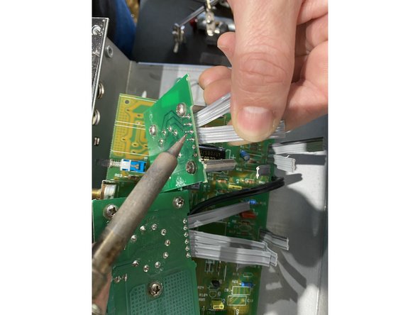
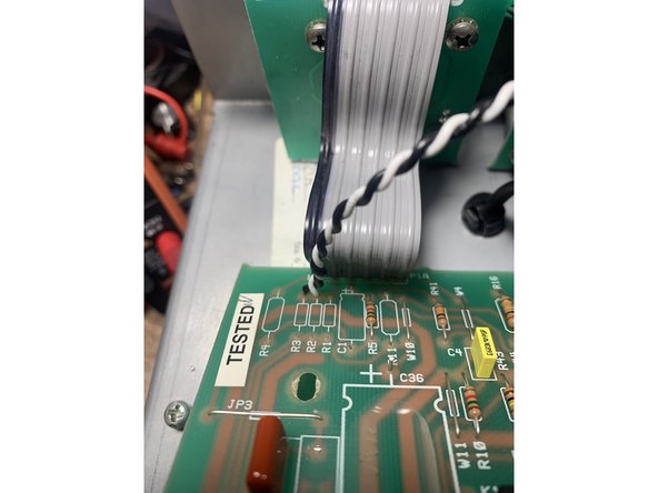
Remove the ribbon cable and shielded coax connected between the main PCB and the V1 PCB.
-
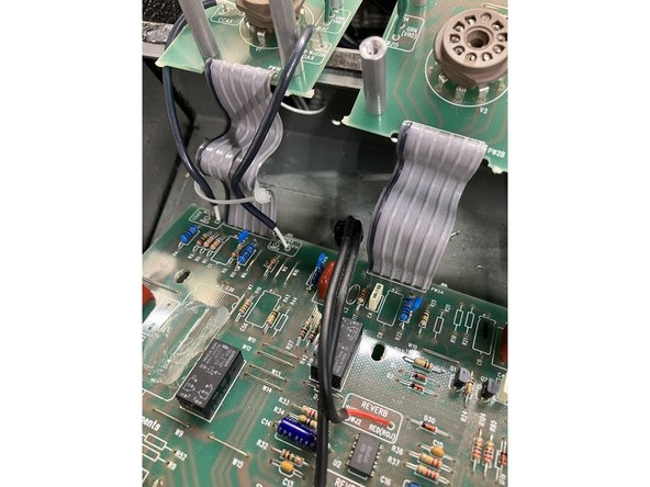
Pro Tip for ribbon cable removal: Use kitchen shears to cut the ribbon cable in half and then cut lengthwise all the way to the board separating each ribbon cable into groups of two and then clip the leads as close to the pcb as you can ON THE SOLDER SIDE of the board without damaging the solder pads.
-
Pro Tip continued: Add a little lead based solder to the solder joint. Gently tug on one of the separated ribbon cables while heating the solder connection with your soldering iron.
-
-
-
The ribbon cable connection on the main PCB is PW1A. The ribbon connection on the V1 tube PCB is PW1B. Looking at the front of the amp the pads are numbered left to right. The shielded coax connections are WJ19 A and WJ21A. The tube pins are numbered clockwise if you are looking at the bottom of the socket/ front of the amp
-
For solder joints to the tube pin PCB connections you will have a better connection if you remove the solder first and push the wire into the pad with the tube pin connection. Use a lot of heat.
-
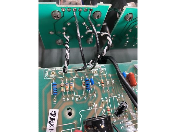
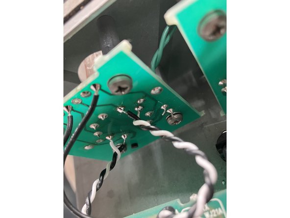
Twist together two different colored 80mm wires. Using that 80mm long twisted wire pair connect WJ19 - A on the main PCB to Pin 2 and PW1A - 1 to pin one.
-
IT IS VERY IMPORTANT THAT THE CONNECTIONS IN THIS STEP ARE CORRECT! take your time and refer to the photos.
-
Using an 80mm long lead connect PW1A - 3 on the main PCB to PW1B - 3 on the V1 PCB
-
Using an 80mm long lead connect PW1A - 6 on the main PCB to PW1B - 6 on the V1 PCB
-
Twist together two different colored 80mm wires. Using that 80mm long twisted wire pair connect WJ21 - A on the main PCB to Pin 7 and PW1A - 4 to pin 6.
-
See photos. What we're doing here is using the out of phase plate voltage as a sort of shield for the grid signal. It's a good idea for lower noise to keep the lone cathode wires ( V1 pcb pads 3 and 6) away from the twisted pairs.
-
-
-
For OD+ Upgrade skip this step and go to step 14
-
With the control panel facing you remove left to right: R4, C23, C1, R11, R52, R9, C56( earliest Hot Rods don't have C56), R44, R16, C3, C8, R22, R20, R19, R21, and C9.
-
Near the pots remove: left to right: C7, R12, C5, R105, C6, C11( behind the master volume), R103( behind the reverb pot.
-
For Hot Rod IV owners also remove R27 on the tube PCB
-
R103, R105, C1, C3, C9, and C11 are not replaced with components and will be empty when the mods are done.
-
-
-
With the control panel facing you remove left to right: C1, R52, R9, C56( earliest Hot Rods don't have C56), R44( only if your R44 is 180k), C3, C8, R20, R19, R21, and C9.
-
Near the pots remove: left to right: C5, R12, R105, C6,
-
For Hot Rod IV owners also remove R27 on the tube PCB
-
R103, R105, C1, C3, C9, and C11 are not replaced with components and will be empty when the mods are done.
-
-
-
SKIP THIS STEP IF YOU ARE INSTALLING THE OD+ Upgrade kit
-
Remove: Power Resistors R78 & R79
-
-
-
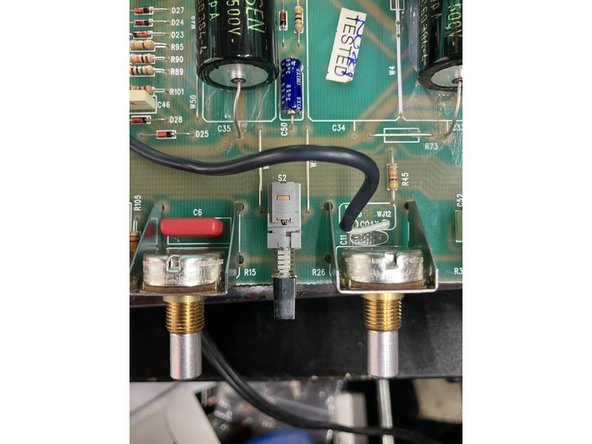
Remove volume( R6), mid(R15), and master volume(R26) pots.
-
For the OD+ Upgrade only remove the volume and mid pots, you should have already installed the 100KA10 master volume pot when you did the previous mods.
-
Easiest to remove all the solder from the frame and three pot pins and then gently pull away from the PCB. NEVER heat the solder and try to pull the pot out - it WILL lift the traces.
-
-
-
SKIP THIS STEP IF YOU ARE INSTALLING THE OD+ Upgrade kit
-
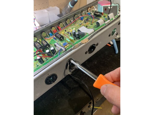
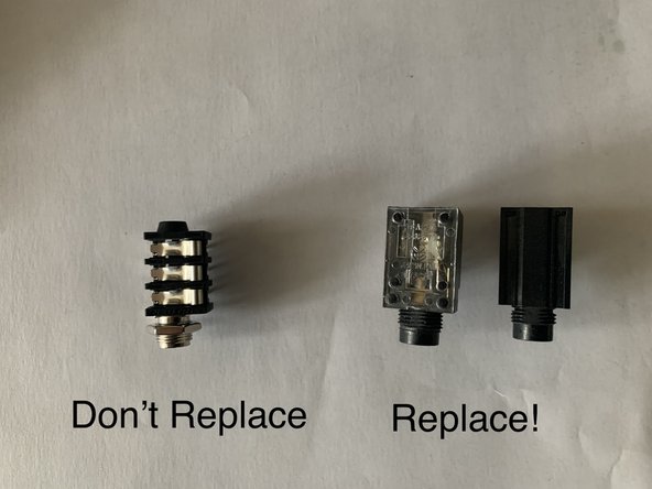
Remove the input jacks. The input jacks are snapped into the PCB. It's easiest to remove all the solder from the solder side and then remove the jack
-
If you have a Hot Rod Deluxe or Deville III or later with Neutrik style pcb mounted jacks we DO NOT recommend putting new jacks in. These jacks are of high quality and the Fromel input jack pcb will only fit upside down which reverses inputs 1 and 2, leftmost jack will be quieter. You CAN do it if you like, just keep this in mind.
-
-
-
The component leads may need to be bent to match the holes in the PCB. Resistors, film, and MLCC capacitors don't have a polarity so it doesn't matter which lead is in which hole
-
Electrolytic caps DO have a polarity and will need to be installed with the positive side in the positive hole in the PCB. Incorrect polarity can damage Electrolytic caps and even cause them to explode! Input jacks will need to be installed exactly per instructions too
-
Some of the resistors we source may be smaller than others yet are still rated at the same wattage. A good way to tell is to check the lead thickness if the resistor has a smaller form factor, the lead thickness will be similar to a larger version of that resistor.
-
Some of the other components may not match the photos exactly in the kit, again it comes down to what we can source with the same or better quality, we are always trying different components and choosing the ones that will work and sound the best!
-
The small blue MLCC caps can be identified by the 3 number cap code printed on them in very very small lettering, I have to use shop glasses, a magnifying glass, AND a bright light to see the numbers. The first two numbers are the cap value and the third is the decimal point. The 270pf is marked 271, .0022uf is 222( .0022uf =2200pf), etc
-
-
-
Install: 270pf MLCC in C7, 15mm .022 Wima in C5, 10mm .022 in C6, and 1/2W 56k in R12
-
For OD+ Upgrade: install 15mm .022 in C5, 10mm .022 in C6, and 1/2w 56k in R12
-
-
-
SKIP THIS STEP IF YOU ARE INSTALLING THE OD+ Upgrade kit
-
The capacitor in this step needs to be installed with the correct polarity. Failure to do this could cause dangerous and catastrophic results
-
To install the capacitors with the correct polarity the circuit board will have a "+" sign on it closest to where the positive lead of the cap should be installed
-
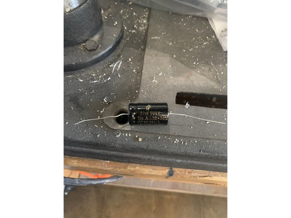
Axial capacitors have an indented ring on the positive side and a "-" sign in an arrow pointing to the negative lead. Radial Capacitors have a longer positive lead and there is a "-" sign in a band closest to the negative lead.
-
I highly recommend fitting the cap and then putting a small blob of silicon RTV under where the cap will be to secure it before soldering the cap.
-
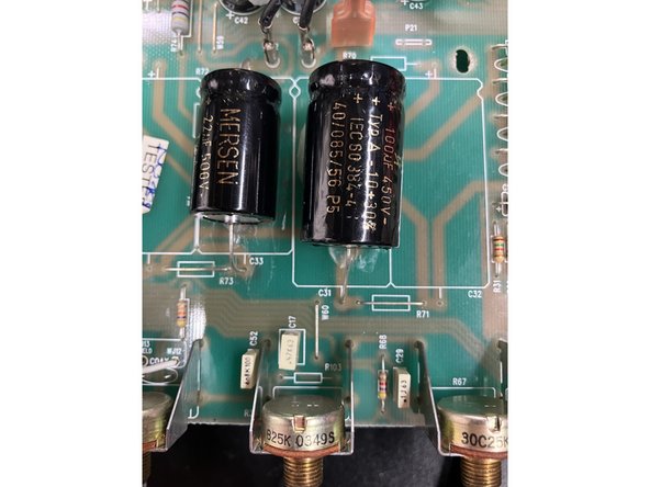
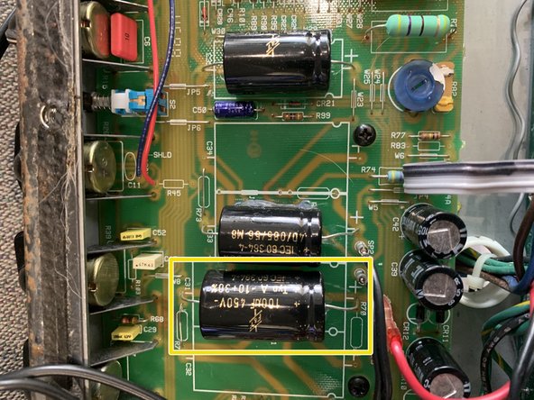
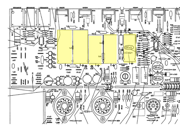
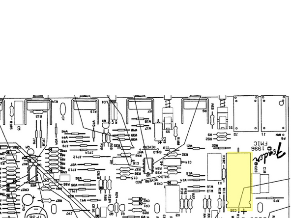
Replace C31 with the 100uf/ 450V cap
-
-
-
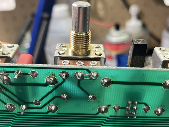
Install 100kA pots in R6, R15, and R26 - Volume, mid, master volume. For OD+ Upgrade only install in R6 and R15.
-
On volume pot(R6) leave pins 2 and 3 unsoldered - you'll see why in the next step
-
Remove the nuts and washers from the pots - it's easy to forget they're there and can make for a frustrating time putting things back together!
-
Using a lead clipped from an installed component to bridge pins 2 and 3 on the mid pot(R15).
-
Bridging pins 2 & 3 of the mid pot will increase the range of your mid control, allowing you to get vintage black panel tones with the mid pot set low, be aware, however that the amp will not make any sound with all the tone controls turned all the way down, just make sure to have your tone controls turned up when testing the amp post mods.
-
These mods will give your mid control a much wider range: between all the way down to halfway up the mid pot will work similar to stock, but as you turn it higher it will take more of the tone stack out of the circuit increasing gain and mids. Sort of a black panel to tweed control!
-
-
-
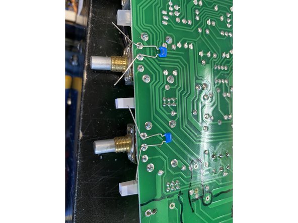
Install 100pf mlcc caps across pins 2 and 3 of the Volume(R6) and Drive(R7) pots on the solder side of the main PCB. For OD+ Upgrade you should only need to install the 100pf on the volume pot, drive pot should already have it installed.
-
After installing clip the leads flush to the solder. Make sure they're not hanging past at all to short on the chassis
-
-
-
SKIP THIS STEP IF YOU ARE INSTALLING THE OD+ Upgrade kit
-
For Hot Rod Deluxe only: Install the 470 ohm power resistors at R78 and R79. Install them so that they sit 1/4 inch off the PCB
-
For Hot Rod Deville only: Install the 330 ohm power resistors at R78 and R79. Install them so that they sit 1/4 inch off the PCB
-
Make sure to leave at least 1/8 to 1/4 of an inch between the body of the resistor and where you bend the lead
-
-
-
Install 1/2W 100k metal film resistor in R4. For OD+ Upgrade R4 should already have been installed previously.
-
Install 1/2W 100k metal film resistors with 470pf MLCC cap in parallel in R11, R16 and R22
-
For R16 and R22 I find it easiest to fit the 100k resistor in the PCB then pull it back out and wrap the MLCC leads around the resistor leads and solder them - see photo- then clip the MLCC leads and install
-
For OD+ Upgrade: solder the 470pf caps across R11, R16, and R22 in parallel.
-
If you are primarily using the Drive and More Drive at stage/ with a drummer volumes( Master Volume at 6 or higher) I would recommend only putting a 470pf in parallel with R22( just used in the Drive circuit), I think it sounds better.
-
If this is too bright or you're using it primarily at lower volumes install the 470pf in parallel with R16 or R11 and R16 as well. These caps attenuate highs starting about 3khz, removing fizz.
-
-
-
Install 680k resistor in R9
-
Install 56k 1/2W metal film resistor in R44 if you have an early Hot Rod with 180k in R44, later Hot Rods already have a 56k so you don't need to change it
-
-
-
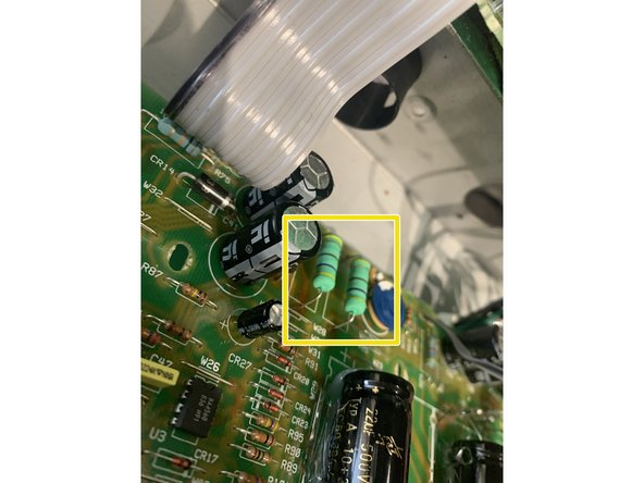
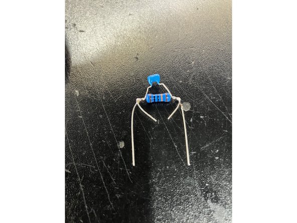
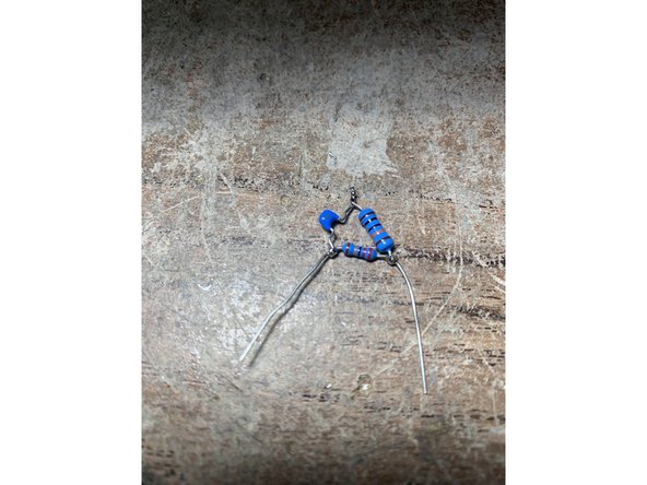
In R52 install 220K resistor in parallel with a .0022uf cap that's in series with a 100k resistor . See pic.
-
Install 10mm .022uf cap in C23. For OD+ Upgrade your amp should already have this cap installed previously
-
Install 4.7uf cap in C56. If your amp doesn't have a C56 you'll need to solder the cap to R10( see pic for example of the polarity - you'll need to solder it though!)
-
-
-
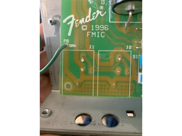
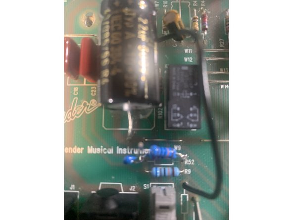
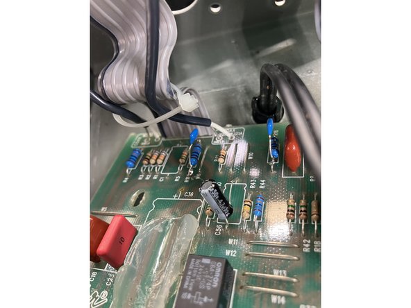
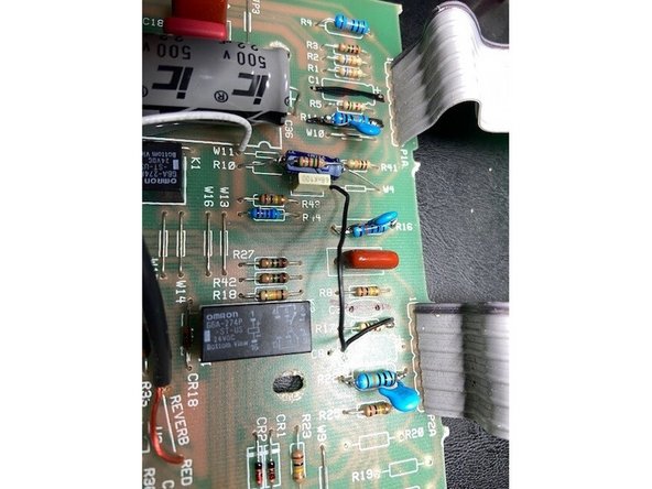
If your amp looks like the one in the photo it's an early Hot Rod that has a factory mod that will need to be removed for the mods to work like they should.
-
Remove the jumper from the top of W9 to R12. Do not cut R12.
-
Cut the cap that's in parallel with R10 off( leave the leads) and put that 1.5k resistor in R10 with the 4.7uf from the kit in parallel with it. The ground(-) lead for the 4.7uf should be pointed towards the controls
-
Jumper W9( you can use the wire removed from W9 to R12, cut it to fit)
-
See second photo for pic of the completed step
-
-
-
Install 3.3uf in C8
-
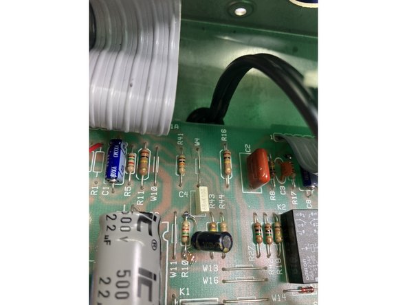
Install .0022uf cap in series with 470k resistor in R20. Solder one lead of a 100k resistor to the junction between .0022uf cap and 470k and the other lead to the top hole of R19. See pic.
-
Install 4.7K resistor in R21
-
-
-
Remove R3, R2, and R1.
-
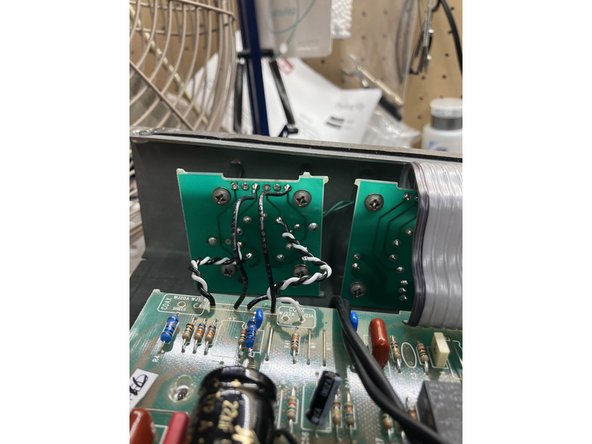
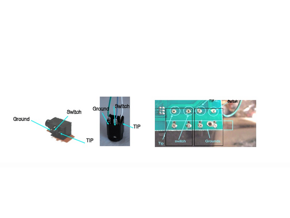
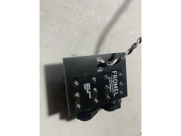
Twist the120mm leads.
-
Solder one end of the twisted pair to the jack PCB at SIG and GND as shown in the photo and the other ends into R2 and R3: the lead from the jack PCB SIG goes to the bottom of R2 and GND goes to the bottom of R3.
-
-
-
Only follow this step if you purchased the OD+ Supreme mod kit and are working on a Hot Rod Deluxe. For Hot Rod Deville owners skip this step, the next step is for you
-
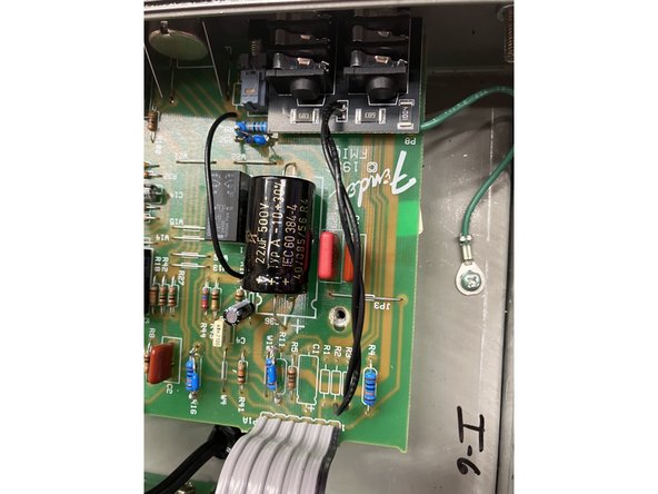
Remove C33, C35 and C36
-
Install 22uf/ 500V caps at C33, C35, and C36
-
It's a good idea to use a dab of silicone RTV under each cap after you've fitted it, but before you've soldered it, to secure it.
-
All of the capacitors on this step need to be installed with the correct polarity. Failure to do this could cause dangerous and catastrophic results
-
To install the capacitors with the correct polarity the circuit board will have a "+" sign on it closest to where the positive lead of the cap should be installed
-
Axial capacitors have an indented ring on the positive side and a "-" sign in an arrow pointing to the negative lead. Radial Capacitors have a longer positive lead and there is a "-" sign in a band closest to the negative lead.
-
-
-
Only follow this step if you purchased the OD+ Supreme mod kit and are working on a Hot Rod Deville. For Hot Rod Deluxe owners skip this step.
-
Install 100uf/ 450V caps in C31 and C32, 47uf/ 500V caps in C33 and C34, and 22uf/ 500V caps in C35 and C36
-
It's a good idea to use a dab of silicone RTV under each cap after you've fitted it, but before you've soldered it, to secure it.
-
All of the capacitors on this step need to be installed with the correct polarity. Failure to do this could cause dangerous and catastrophic results
-
To install the capacitors with the correct polarity the circuit board will have a "+" sign on it closest to where the positive lead of the cap should be installed
-
Axial capacitors have an indented ring on the positive side and a "-" sign in an arrow pointing to the negative lead. Radial Capacitors have a longer positive lead and there is a "-" sign in a band closest to the negative lead.
-
-
-
Carefully put the Main PCB back into place making sure the pots, switches, and LED all line up with and fit snugly to the control panel.
-
Replace all the PCB mounting screws
-
Re-install the Tube PCBs
-
Dress the wires between the Main PCB and Tube PCB, make sure they have plenty of distance from each other and aren't resting on any parts.
-
Mount the new input jacks in the chassis. Use the supplied shoulder washer on the jack and the flat washer on the front of the chassis. If there isn't enough room for the metal washer you can leave it off. Isolating the jack from the chassis can prevent noise from ground loops.
-
Re-install the washers and nuts for the pots and other jacks.Do not over tighten the jacks for the effects loop or footswitch jacks
-
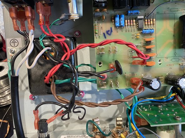
Dress the transformer leads. Instead of replacing the cable ties we removed we're going to use standard wiring techniques for proper amp lead dress. Twist all AC pairs together: twist green wires together, red, and brown.
-
Re-install the control knobs
-
-
-
Mount the chassis back in the cabinet if you took it out
-
STOP! DOUBLE CHECK ALL YOUR WORK
-
Replace the back panel and tighten the chassis screws if you loosened them
-
Enjoy creamy boutique overdrive, luscious cleans, and an amp that sounds great and is easy to dial in at all volumes!
-


Cancel: I did not complete this guide.
2 other people completed this guide.

8 Comments
Followed these instructions exactly on an 08 deluxe and I’ve only got 1 channel now. Mildly annoyed.
James Patterson - Resolved on Release Reply
Mapped it all out on the schematic and I think I may have an unrelated switching issue.
I installed the Hot Rod Deville Supreme OD+ kit on my mid-90's HR Deville. Sounding great so far!
Noticing 2 things
1) The bright switch no longer has any effect when pushed on/off. (guessing this is related to the R10/4.7uf mod)?
2) The new input jack pcb board seems to pop when plugging in the 1/4 cable when the amp is on (i.e switching between input 1 vs 2)
Jordan Stone - Resolved on Release Reply
Client very happy.
Might put at the end "If you you have parts left over...you did it wrong."
Dwayne Williams - Resolved on Release Reply
In Step 13 C1 (V1a cathode) is removed and I cannot find where it is replaced
Michael Baker - Resolved on Release Reply