
Introduction
Hot Rod Deluxe Mod kit
Tools
Parts
- Wima .015 10mm Cap
- Wima .022 10mm Cap
- Wima .1 15mm Cap
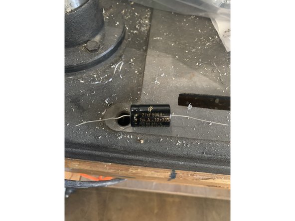
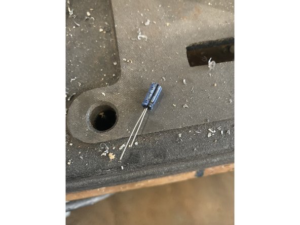
- 270pf 500v Cap
- 100pf 500v Cap × 2
- 100k 1/4 Watt Resistor
- 56k 1/2 Watt Resistor
- 82k 1/2 Watt Resistor
- 100k 1/2 Watt Resistor × 5
- 470 Ohm 5 Watt Resistor × 2
- 100k 16mm Audio Taper Pot
- 100uf 450v Axial Capacitor
- 3" lead × 27
- 4" lead × 2
- 120mm lead × 2
-
-
You can buy the kit from us here: https://fromelelectronics.com/collection...
-
WARNING Performing these modifications WILL void the warranty on your amp. Working on amps can be DEADLY if you do not take proper precautions.
-
Follow these instructions very carefully. If at any point in the mod process you are at all unsure of your ability to do these mods take your amp to a professional to be modded. You can also send your amp to me to be modded.
-
No Warranty - This kit and the instructions do not include a warranty of any kind. The modifications to your amplifier are at your own risk and you agree to hold harmless the seller of this kit against any and all claims
-
Tube amps contain parts that operate at very high temperatures and deadly voltages.
-
There a couple of differences between the Hot Rod Deluxe and Deville and depending on which amp you're working on there will be different instructions you'll need to follow
-
These modifications are for the Hot Rod Deluxe and Deville versions I, II, and III. If you have a Hot Rod Deluxe or Deville IV use the Legacy instructions: Fender HRDX-Manual-2020(scroll to the end of these instructions)or Hot Rod Deville Legacy ( Pre April 2022).
-
-
-
Time to make sure you have the correct kit and all the parts you need to install it before getting started.
-
These instructions are for kits sold between April 2022 and early September 2024 if your kit was purchased after September 2024 and is the Supreme OD+ kit your instructions are here: Hot Rod Deluxe/ Deville Supreme Hot Rod Deluxe/ Deville - OverDrive+ (OD+) - for Hot Rod Deluxe/ Deville I-IV
-
Now check the parts you have against the list of parts at the beginning of these instructions. If they don't match please let us know at fromelelectronics.com
-
-
-
Unplug the amp and place on a level surface
-
Remove the chicken head control knobs by loosening the set screws. Remove the nuts and washers holding the potentiometers and jacks on the top panel
-
Remove the screws holding on the back panel and remove the panel. If the back panel does not come off easily you can loosen the chassis screws on the side of the amp about a half turn each
-
-
-
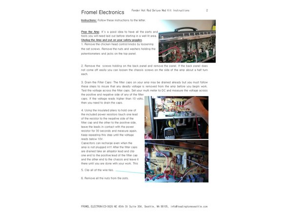
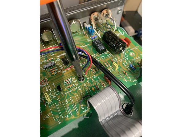
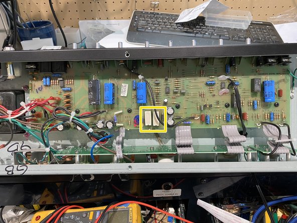
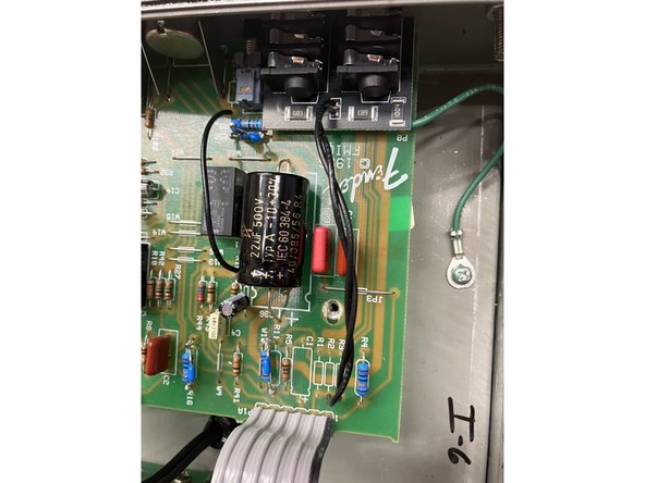
Check to see if your caps are charged, set your multi-meter to DC and measure the voltage at the positive side of the filter cap closest to the power switch
-
If you measure more than 12VDC, you need to drain the caps. If there are less than 12VDC you may proceed to the next step
-
FAILURE TO DO THIS STEP COULD CAUSE INJURY OR DEATH BY ELECTROCUTION!
-
-
-
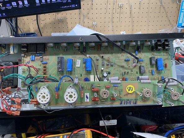
Remove the smaller tube PCB that supports the tube sockets: Remove the tubes and then remove the small black screws that hold both the larger tube PCB and the smaller V1 tube PCB to the chassis. Gently lift both tube PCBs free of the chassis
-
-
-
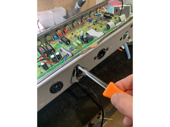
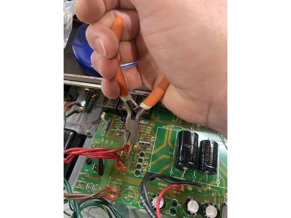
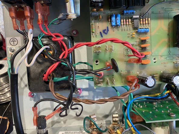
Unplug all of the quick connect leads from the choke, power, and output transformers and the switches by pulling on the quick connect firmly with steady pressure while gently rocking it from side to side. Using a pair of angled needle nosed pliers makes it much easier
-
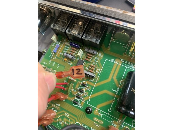
As you remove each lead be sure to mark the terminal number on the lead with a fine point Sharpie pen so you will know where to plug it back in when the amp mods are done
-
Remove all PCB standoff screws and the solder terminal screw connecting the green ground wire from the Main Pcb near the input jacks to the chassis.
-
-
-
Pull gently on the PCB to make sure that it's not stuck to any of the standoffs where screws had been holding it
-
Press the wires from the output transformer and reverb as far away from the PCB and as close to the chassis as possible. The edge of the PCB will need to come down to the bottom of the amp where the tube PCB was before the pots will be able to clear the chassis
-
Using gentle pressure on the top of the board and making sure it's not getting hung up on any wires push it towards the back of the chassis( where the tube board was) until the pots have cleared the top of the chassis then pull the board up to you to expose the solder side of the board
-
DO NOT PUT ANY PRESSURE ON ANY COMPONENTS INCLUDING THE FILTER CAPS WHEN TRYING TO MOVE THE BOARD
-
-
-
Make sure your soldering iron is not too hot. The solder pads on the PCBs are fragile and prone to separating from the PCB, remove components with care and never use force
-
Clip the leads where they meet the PCB on the component side and then remove the solder and rest of the lead from the solder side of the PCB using a solder sucker or de-solder braid
-
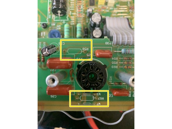
Remove Resistors R57 and R58 on the Tube PCB
-
-
-
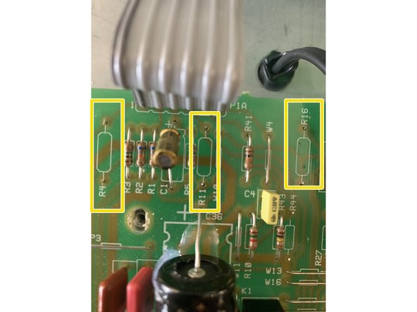
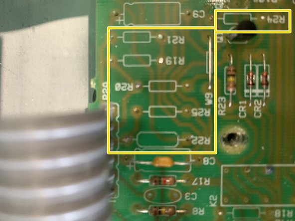
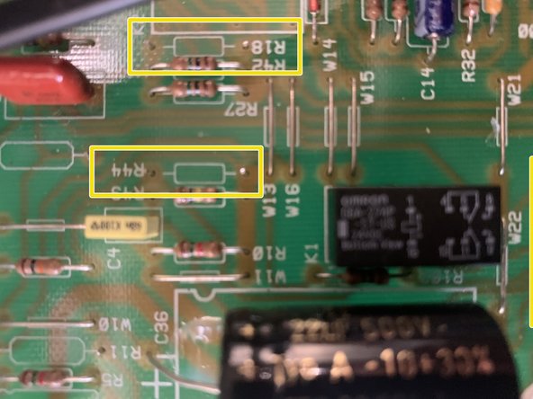
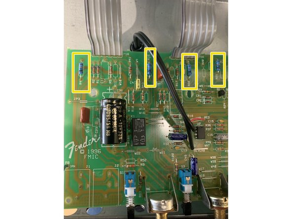
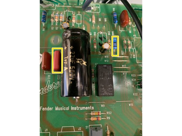
Remove Resistors: R4, R11, R12, R16, R18, R19, R20, R21, R22, R24, R25, R44
-
-
-
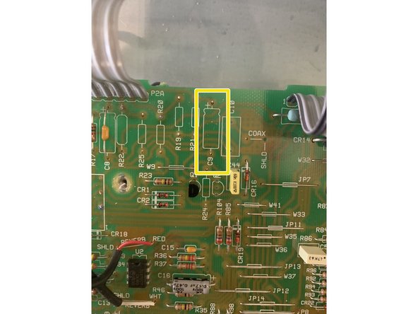
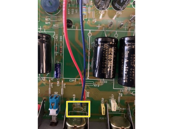
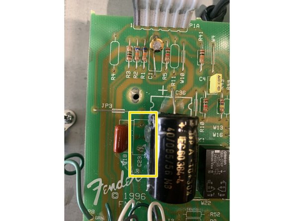
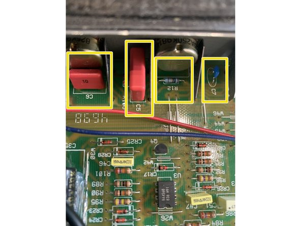
Remove Capacitors: C5, C6, C7, C9, C11, C23, and C31( DO NOT REMOVE C31 if you are doing a Hot Rod Deville Complete or Supreme mod)
-
-
-
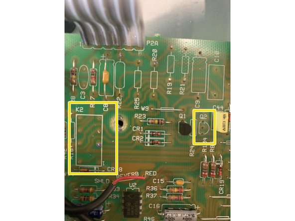
Remove Transistor Q2 and Relay K2
-
Pro Tip: Easiest to desolder the relay from the solder side to remove.
-
-
-
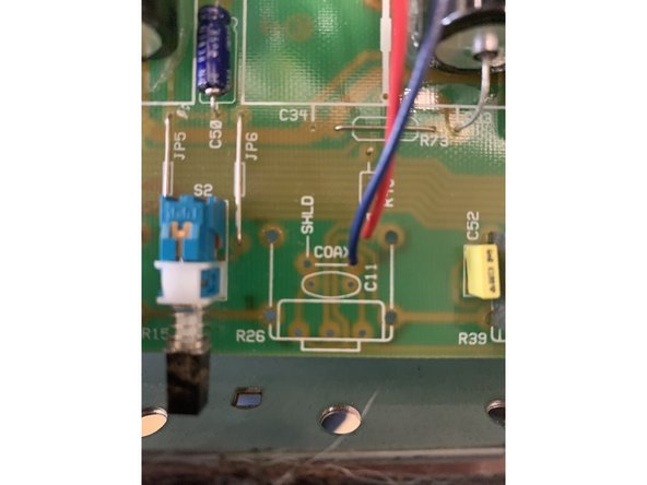
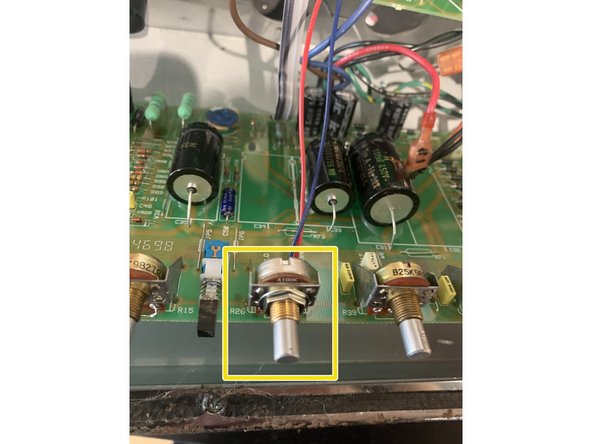
Remove Master Volume Pot and assembly - R26.
-
Pro Tip: It's easiest to remove all the solder from the solder side and then remove the Pot
-
-
-
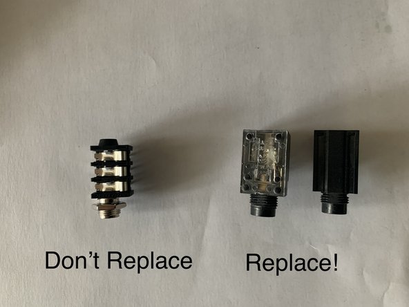
Remove the input jacks. The input jacks are snapped into the PCB. It's easiest to remove all the solder from the solder side and then remove the jack
-
If you have a Hot Rod Deluxe or Deville III or later with Neutrik style pcb mounted jacks we DO NOT recommend putting new jacks in. These jacks are of high quality and the Switchcraft style jacks in the kits will not fit very well and can cause the main PCB to bend and be stressed by their installation!
-
-
-
The component leads may need to be bent to match the holes in the PCB. Resistors, film, and MLCC capacitors don't have a polarity so it doesn't matter which lead is in which hole
-
Electrolytic caps DO have a polarity and will need to be installed with the positive side in the positive hole in the PCB. Incorrect polarity can damage Electrolytic caps and even cause them to explode! Input jacks will need to be installed exactly per instructions too
-
-
-
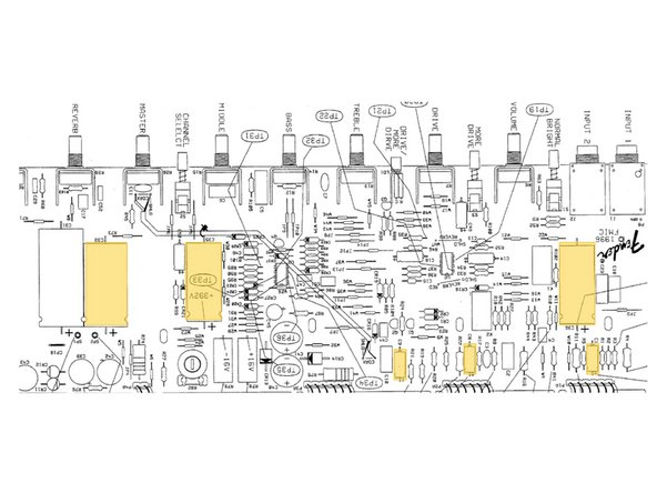
Install the .1 WIMA box film cap at C5
-
Install the .015 WIMA box film cap at C6
-
Install the 270pf MLCC cap at C7
-
Install the 100k 1/4W resistor in R12 ( the smallest 100k resistor)
-
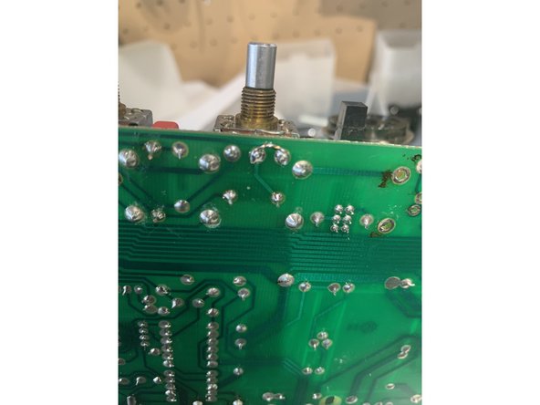
Use a lead clipped from one of the components you installed to bridge pins 2 and 3 on the Mid pot on the solder side of the board the holes closest to the Master Volume pot. It's best to remove the old solder before installing the bridge.
-
After these mods your amp will not make sound with all of the tone controls all the way down. This is on purpose! What you're doing is changing the tone stack to a vintage style which gives you a greater range on the mid pot.
-
-
-
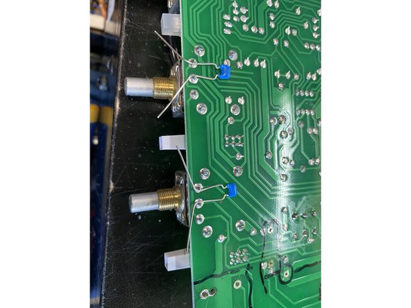
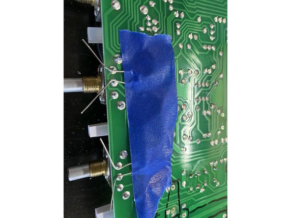
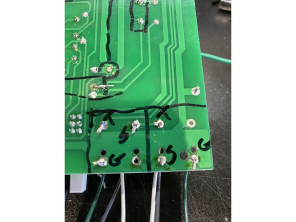
Install 100pf mica or mlcc cap across pins 2 and 3 of the Volume and Drive pots on the solder side of the main PCB
-
Pro tip: Use low tack painters tape to hold the 100pf caps in place while you solder!
-
-
-
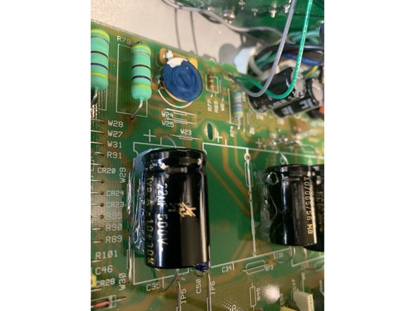
For Hot Rod Deluxe only: Install the 470 ohm power resistors at R78 and R79. Install them so that they sit 1/4 inch off the PCB
-
For Hot Rod Deville only: Install the 330 ohm power resistors at R78 and R79. Install them so that they sit 1/4 inch off the PCB
-
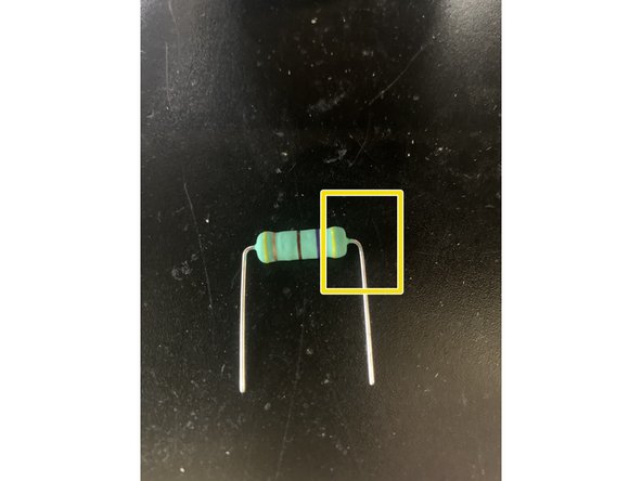
Make sure to leave at least 1/8 of an inch between the body of the resistor and where you bend the lead
-
-
-
On the Tube PCB install the 82k 1/2W resistor at R57 and a 100k 1/2W resistor at R58
-
On the Main PCB install 100k resistors at: R4, R16, R21, and R22
-
-
-
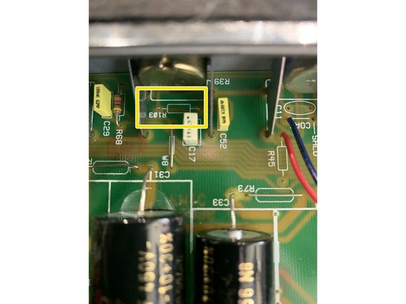
Remove R103 just under the Reverb pot.
-
I recommend just clipping both leads on the component side of the Main PCB
-
-
-
If your kit came with open frame jacks follow the instructions below
-
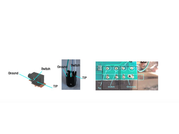
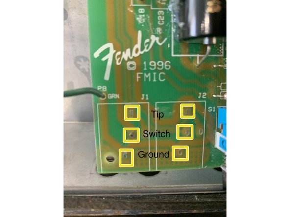
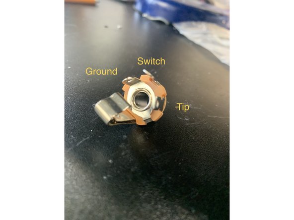
Solder the three leads to the input jack and install on Main PCB
-
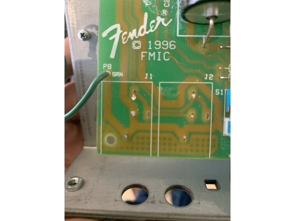
There are two different styles of input jack PCB connections Fender used on these amps. Use the connections marked in the photo that matches your PCB
-
-
-
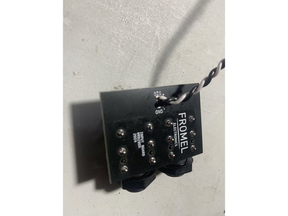
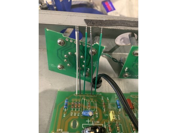
If your kit came with the Fromel input jack PCB follow the instructions below
-
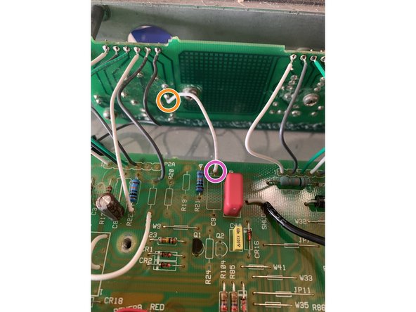
Remove R3, R2, and R1.
-
Twist the120mm leads.
-
Solder one end of the twisted pair to the jack PCB at SIG and GND as shown in the photo and the other ends into R2 and R3: the lead from the jack PCB SIG goes to the bottom of R2 and GND goes to the bottom of R3.
-
-
-
Only follow this step if you purchased the Supreme mod kit and are working on a Hot Rod Deluxe. For Hot Rod Deville owners skip this step, the next step is for you
-
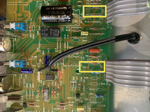
Remove capacitors: C1, C8, C9, C33, C35, C36, C56( C56 is only on some later models)
-
Install 22uf/ 25v at C1 and C56( if your amp has that cap). Install 1uf/ 25v at C8.
-
The voltage rating on caps for C1, C8, and C56 in the kits can be anywhere from 25V to 63V for this part depending on our supplier. This voltage rating is a maximum working voltage and for where they are used in the circuit they will see less than 10V.
-
Install 22uf/ 500v at C33, C35, C36
-
All of the capacitors on this step need to be installed with the correct polarity. Failure to do this could cause dangerous and catastrophic results
-
To install the capacitors with the correct polarity the circuit board will have a "+" sign on it closest to where the positive lead of the cap should be installed
-
Axial capacitors have an indented ring on the positive side and a "-" sign in an arrow pointing to the negative lead. Radial Capacitors have a longer positive lead and there is a "-" sign in a band closest to the negative lead.
-
-
-
Only follow this step if you purchased the Supreme mod kit and are working on a Hot Rod Deville. For Hot Rod Deluxe owners skip this step.
-
Remove capacitors: C1, C8, C9, C31, C32, C33, C34, C35, C36, C56( C56 is only on some later models)
-
Install 22uf/ 25V in C1 and C56( if your amp has that cap)
-
Install 1uf/ 50V in C8
-
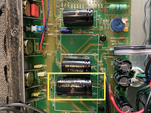
Install 100uf/ 450V caps in C31 and C32, 47uf/ 500V caps in C33 and C34, and 22uf/ 500V caps in C35 and C36
-
All of the capacitors on this step need to be installed with the correct polarity. Failure to do this could cause dangerous and catastrophic results
-
To install the capacitors with the correct polarity the circuit board will have a "+" sign on it closest to where the positive lead of the cap should be installed
-
Axial capacitors have an indented ring on the positive side and a "-" sign in an arrow pointing to the negative lead. Radial Capacitors have a longer positive lead and there is a "-" sign in a band closest to the negative lead.
-
-
-
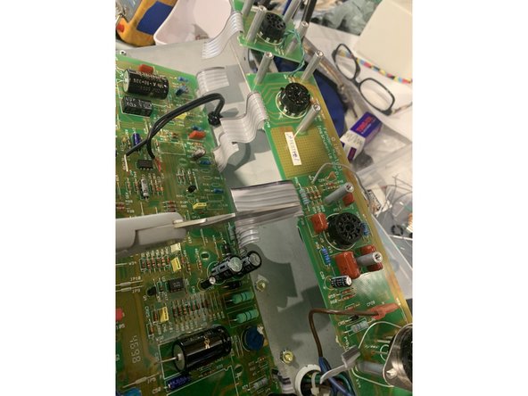
Remove ribbon cables connecting the Tube PCB to MAIN PCB
-
If your amp has shielded coaxial cable between the Main PCB and Tube PCB DO NOT remove it.
-
Pro Tip for ribbon cable removal: Use kitchen shears to cut the ribbon cable in half and then cut lengthwise all the way to the board separating each ribbon cable into groups of two and then clip the leads as close to the pcb as you can ON THE SOLDER SIDE of the board
-
Pro Tip continued: Add a little lead based solder to the solder joint. Gently tug on one of the separated ribbon cables while heating the solder connection with your soldering iron.
-
Remove the solder from the solder pads on the tube PCB and Main PCB
-
-
-
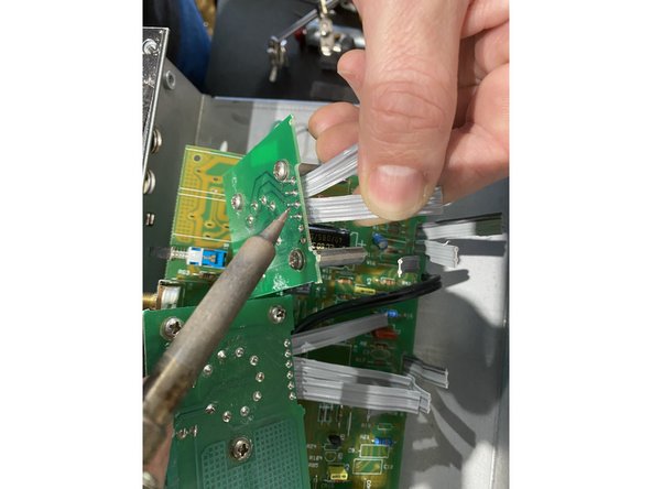
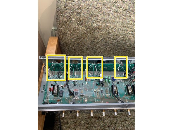
Connect the supplied pre-stripped short wires between the Main PCB and Tube PCB
-
How we're talking about where things are at!: Top of the Main PCB is the side with the pots, Bottom is the side closest to the Tube PCB. Solder pads connecting the tube board we refer to by tube and number counting left to right, for example Tube PCB V1 - 5 is the 5th pad from the right on the first tube.
-
Main PCB solder pads are marked next to each group of holes and numbered left to right: P1A, P2A, P3A, P4A and then each hole in the group is numbered left to right
-
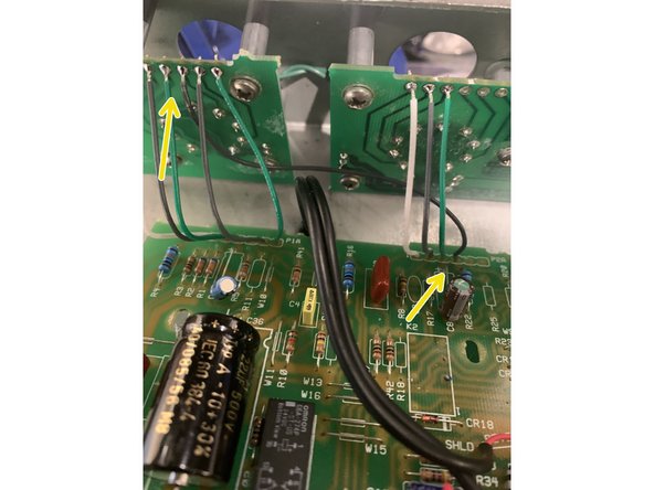
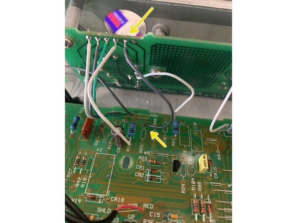
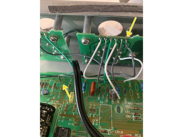
With the front panel facing you and counting from the left install wires 1, 2, 3, 5, and 6 at connection point PW1A. The wires will fit through the component side of the PCB and be soldered on the solder side.
-
Install wires 1, 2, 3 at connection point PW2A
-
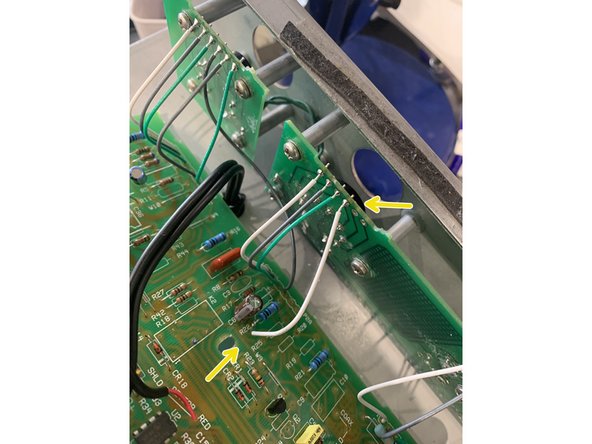
Install all wires at PW3A( 1, 2, 3, 4, 5, 6) and PW4A(1, 2)
-
Once all the wires on the Main PCB have been installed put the Tube PCB where it sits on the back of the chassis and attach it with a couple of screws . All the wires you've just installed can then can be soldered into their matching holes on the solder side of the Tube PCB.
-
Pro Tip: The best way to do this is by inserting a few wires at a time into the holes where the ribbon cable was on the component side of the PCB and Soldering them on the solder side of the PCB. When all wires have been installed on the main PCB solder a few at a time in the holes in tube PCB on the solder side and solder ON THE SOLDER SIDE
-
-
-
Use one of the longer wires cut in half to connect V1 Tube PCB- 4 to Main PCB PW2A - 4
-
We recently changed our kits to have two 4" wires so you won't have to cut an 8" wire in half and strip and tin it, BUT if you have an older kit( bought before March 2023) you'll have the 8" wire.
-
-
-
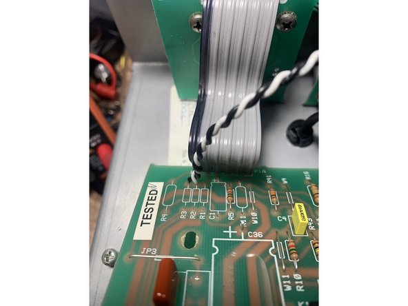
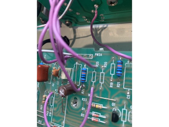
Use one of the smaller wires to connect the pad from V2 - 4 on the Tube PCB to the top side of R22 on the Main PCB
-
-
-
Desolder tube pin 8 on the Tube PCB V2
-
Insert and solder one end of the small wires into the tube pin you just de-soldered
-
Solder the other end of the wire to the bottom hole of C9(removed)
-
-
-
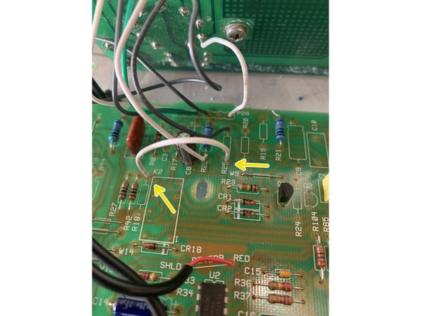
Solder one end of a small wire to pad V2-5 on the Tube PCB and the other end to the bottom hole of R25( removed)
-
-
-
Using the other half of the longer wire( or one of the 4" wires if it's a newer kit) solder one end to Tube PCB V2 - 6 and the other end to the bottom of R11
-
-
-
Using one of the smaller wires jumper bottom of R18(removed) to top of R25(removed) - solder
-
-
-
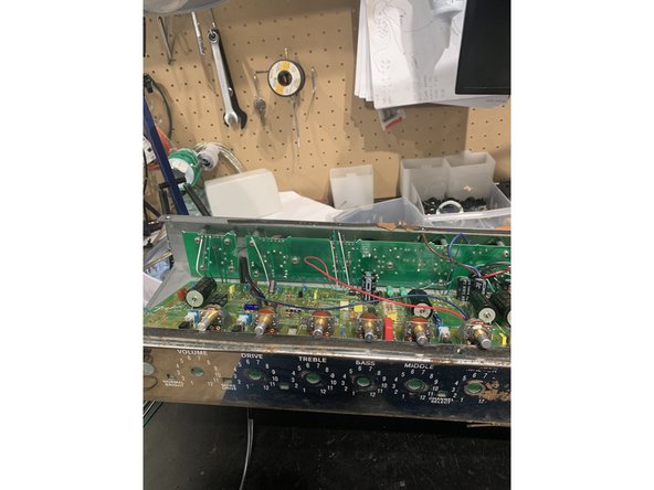
Carefully put the Main PCB back into place making sure the pots, switches, and LED all line up with and fit snugly to the control panel.
-
Replace all the PCB mounting screws
-
Re-install the Tube PCBs
-
Dress the wires between the Main PCB and Tube PCB, make sure they have plenty of distance from each other and aren't resting on any parts.
-
Mount the new input jacks in the chassis. Use the supplied shoulder washer on the jack and the flat washer on the front of the chassis. If there isn't enough room for the metal washer you can leave it off. Isolating the jack from the chassis can prevent noise from ground loops.
-
Re-install the washers and nuts for the pots and other jacks.Do not over tighten the jacks for the effects loop or footswitch jacks
-
Dress the transformer leads!! Poor lead dressing will contribute to the noise in an amp. Instead of replacing the cable ties we removed we're going to use standard wiring techniques for proper amp lead dress. Twist all AC pairs together: twist green wires together, red, and brown. All twisted pairs should cross each other at 90 degree angles.
-
Re-install the control knobs
-
-
-
Mount the chassis back in the cabinet if you took it out
-
Use silicone to glue all filter caps to board as well as the wire for the reverb. You can omit this step if you want, but securing the caps will make your amp sturdier and keep any components from shaking loose
-
STOP! DOUBLE CHECK ALL YOUR WORK
-
Replace the back panel and tighten the chassis screws if you loosened them
-
ENJOY YOUR NEW AMP!
-


We are in the process of making all our instruction sets open source. Our hope is that these guides can improve over time with your feedback. Until the step by step guide is finished you can download the current instruction set.
We are in the process of making all our instruction sets open source. Our hope is that these guides can improve over time with your feedback. Until the step by step guide is finished you can download the current instruction set.
Cancel: I did not complete this guide.
7 other people completed this guide.
Attached Documents

10 Comments
I'm missing an 82K resistor on the DLX III discontinued supreme kit. Got a 10K resistor instead... Oh well, found a MOX 82K in my stash
T.N.Silverman - Resolved on Release Reply
Hi, completed the supreme mod but have zero sound when guitar is plugged in. If I plug into the effects loop input I can hear the guiter. I have checked and re-checked and re-checked. Anywhere I scould look at first?
My work bench is a considerable distance from my computer so I really need to print out these pages but it's a lot in HTML...do you have a PDF for printing for the April 2022 instructions? My amp is a ~2002 Hot Rod Deville with all original parts.
Scott Willits - Resolved on Release Reply